Power conversion apparatus with power saving and high conversion efficiency mechanisms

Active Publication Date: 2016-06-30
POWER FOREST TECH
View PDF13 Cites 3 Cited by
  • Summary
  • Abstract
  • Description
  • Claims
  • Application Information

AI Technical Summary

Benefits of technology

[0023]Based on the above, in the power conversion apparatus provided by the embodiments of the invention, the SR control circuit can detect the time interval of the SR transistor (or the parasitic diode thereof) being turned on or the cycle time of the power conversion of the power conversion apparatus according to the signal from the first drain/source terminal of the SR transistor, so as to determine the status change of the load. When determining that the load is in the light load status, the SR control circui

Problems solved by technology

When the SR transistor is switched between on and off states, the SR controller has to charge or discharge the parasitic capacitor, such that power consumption occurs.
Besides, the SR transistor itself also consumes

Method used


Image

  • Power conversion apparatus with power saving and high conversion efficiency mechanisms
  • Power conversion apparatus with power saving and high conversion efficiency mechanisms
  • Power conversion apparatus with power saving and high conversion efficiency mechanisms

Examples


Embodiment Construction

[0031]In order to make the disclosure more comprehensible, embodiments are described below as examples showing that the disclosure can actually be realized. Wherever possible, the same reference numbers are used in the drawings and the description to refer to the same or like parts.

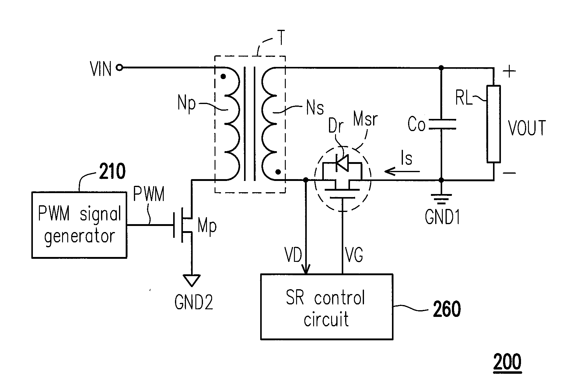
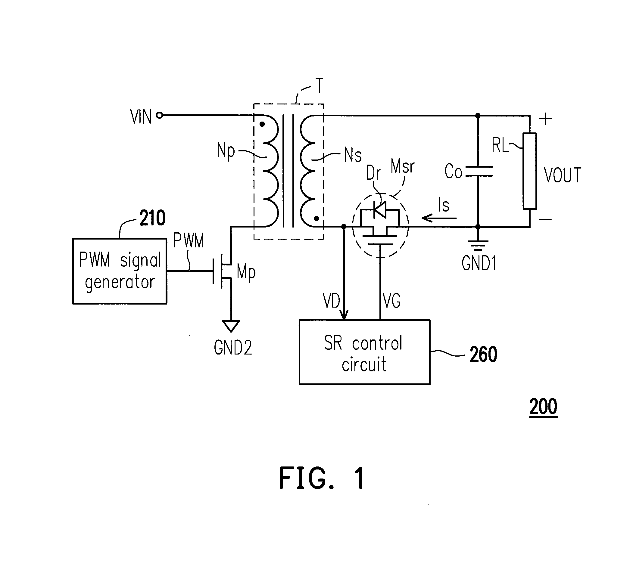
[0032]FIG. 1 is a schematic circuit diagram illustrating a power conversion apparatus 200 according to an embodiment of the invention. Referring to FIG. 1, the power conversion apparatus 200 includes a transformer T, a synchronous rectification (SR) transistor Msr, an SR control circuit 260, a power switch Mp and a pulse width modulation (PWM) signal generator 210. The transformer T includes a primary side Np and a secondary side Ns. A first terminal (e.g., a common-polarity terminal, which is a dotted terminal) of the primary side Np is configured to receive an input voltage VIN, and a first terminal (e.g., an opposite-polarity terminal, which is a non-dotted terminal) of the secondary side Ns is configu...


PUM


Abstract

A power conversion apparatus is provided. The power conversion apparatus includes a transformer, a synchronous rectification (SR) transistor and an SR control circuit. A first terminal of a primary side of the transformer receives an input voltage. A first terminal of a secondary side of the transformer provides an output voltage to a load. A first drain/source terminal of the SR transistor is coupled to a second terminal of the secondary side of the transformer. A second drain/source terminal of the SR transistor is coupled to a first ground terminal. A gate terminal of the SR transistor receives a control signal. The SR control circuit receives a signal of the first drain/source terminal of the SR transistor to determine statuses of the load and generate the control signal. When the load is a light load, the SR control circuit enters a power-saving mode and turns off the SR transistor.

Description

CROSS-REFERENCE TO RELATED APPLICATION[0001]This application claims the priority benefit of Taiwan application serial no. 103146541, filed on Dec. 31, 2014. The entirety of the above-mentioned patent application is hereby incorporated by reference herein and made a part of this specification.BACKGROUND[0002]1. Field of the Invention[0003]The invention is directed to a power conversion technique and more particularly, to a power conversion apparatus with power saving capability and high conversion efficiency.[0004]2. Description of Related Art[0005]Power conversion apparatuses are indispensable parts of electronic apparatuses at present. In a power conversion apparatus controlled based on pulse width modulation (PWM), a secondary side thereof typically includes a rectification diode. Due to the rectification diode in an on state having greater power consumption, a synchronous rectification (SR) transistor with a lower turned on resistance (Rds-on) is adopted in replacement with the r...

Claims


Application Information

Patent Timeline
IPC IPC(8): H02M3/335H02M1/08
CPCH02M3/33592H02M2001/0032H02M1/08H02M1/0032H02M1/0054Y02B70/10
Inventor SHEIN, CHEIN-KUO
Owner POWER FOREST TECH
Why Eureka
Try Eureka