

Switching power supply circuit
- Summary
- Abstract
- Description
- Claims
- Application Information
AI Technical Summary
Benefits of technology
Problems solved by technology
Method used
Image

Examples
first embodiment
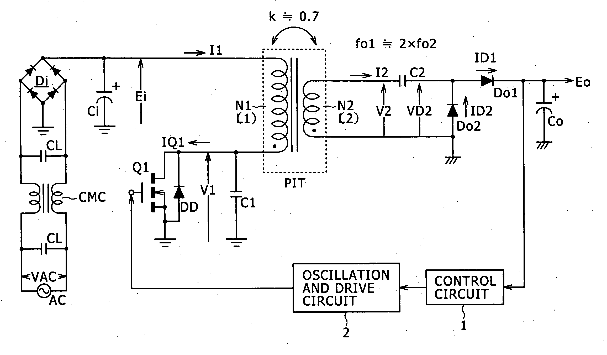
[0063] A circuit diagram of FIG. 1 shows an example of configuration of a power supply circuit as the best mode (an embodiment) for carrying out the invention. The power supply circuit shown in this figure employs a fundamental configuration of a voltage resonant switching converter using a single-ended system.
[0064] In the switching power supply circuit shown in this figure, a set of common mode choke coils CMC and two across capacitors CL are inserted in the line of a commercial alternating-current power supply AC, as shown in the figure. The common mode choke coils CMC and the across capacitors CL and CL form a noise filter for eliminating common mode noise superimposed on the line of the commercial alternating-current power supply AC.
[0065] An alternating input voltage VAC is rectified by a bridge rectifier circuit Di. A smoothing capacitor Ci is charged with the rectified output of the bridge rectifier circuit Di. Thereby a rectified and smoothed voltage Ei is obtained as a v...
second embodiment
[0138]FIG. 6 shows an example of configuration of a power supply circuit according to a Incidentally, in FIG. 6, the same parts as in FIG. 1 are identified by the same reference numerals, and description thereof will be omitted.
[0139] The power supply circuit shown in FIG. 6 has a voltage doubler full-wave rectifier circuit as a secondary side rectifier circuit.
[0140] A secondary winding N2 in the voltage doubler full-wave rectifier circuit is provided with a center tap to be divided into two secondary winding parts N2A and N2B with the center tap as a boundary. The same predetermined number of turns is set for the secondary winding parts N2A and N2B.
[0141] A secondary side series resonant capacitor C2A is connected in series with an end part on the secondary winding part N2A side of the secondary winding N2. A secondary side series resonant capacitor C2B is connected in series with an end part on the secondary winding part N2B side of the secondary winding N2. Thereby, a first s...
third embodiment
[0157]FIG. 7 is a circuit diagram showing an example of configuration of a power supply circuit according to a Incidentally, in FIG. 7, the same parts as in FIG. 1 and FIG. 6 are identified by the same reference numerals, and description thereof will be omitted.
[0158] The power supply circuit shown in FIG. 7 has a bridge full-wave rectifier circuit including a bridge rectifier circuit formed by four rectifier diodes Do1, Do2, Do3, and Do4 as a secondary side rectifier circuit for an isolated converter transformer PIT. This bridge rectifier circuit is formed such that a point of connection between the anode of the rectifier diode Do1 and the cathode of the rectifier diode Do2 is a positive electrode input terminal, a point of connection between the cathode of the rectifier diode Do1 and the cathode of the rectifier diode Do3 is a positive electrode output terminal, a point of connection between the anode of the rectifier diode Do3 and the cathode of the rectifier diode Do4 is a nega...
PUM
 Abstract
Description
Claims
Application Information