Device for generating a dynamic axial thrust to balance the overall axial thrust of a radial rotating machine

Active Publication Date: 2016-07-07
THERMODYN
View PDF3 Cites 10 Cited by
  • Summary
  • Abstract
  • Description
  • Claims
  • Application Information

AI Technical Summary

Benefits of technology

[0011]An embodiment of the invention propose an impeller wheel system which ensures a better axial force compensation, thus making it

Problems solved by technology

Oil bearings are capable of withstanding high loads, but they have to be fed with the lubricating oils, which may be a hindrance in subsea

Method used


Image

  • Device for generating a dynamic axial thrust to balance the overall axial thrust of a radial rotating machine
  • Device for generating a dynamic axial thrust to balance the overall axial thrust of a radial rotating machine
  • Device for generating a dynamic axial thrust to balance the overall axial thrust of a radial rotating machine

Examples


Embodiment Construction

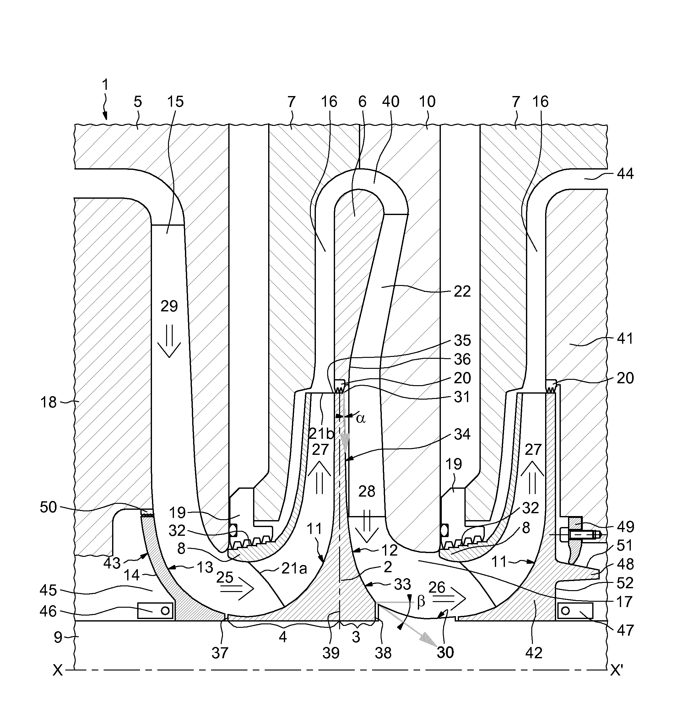
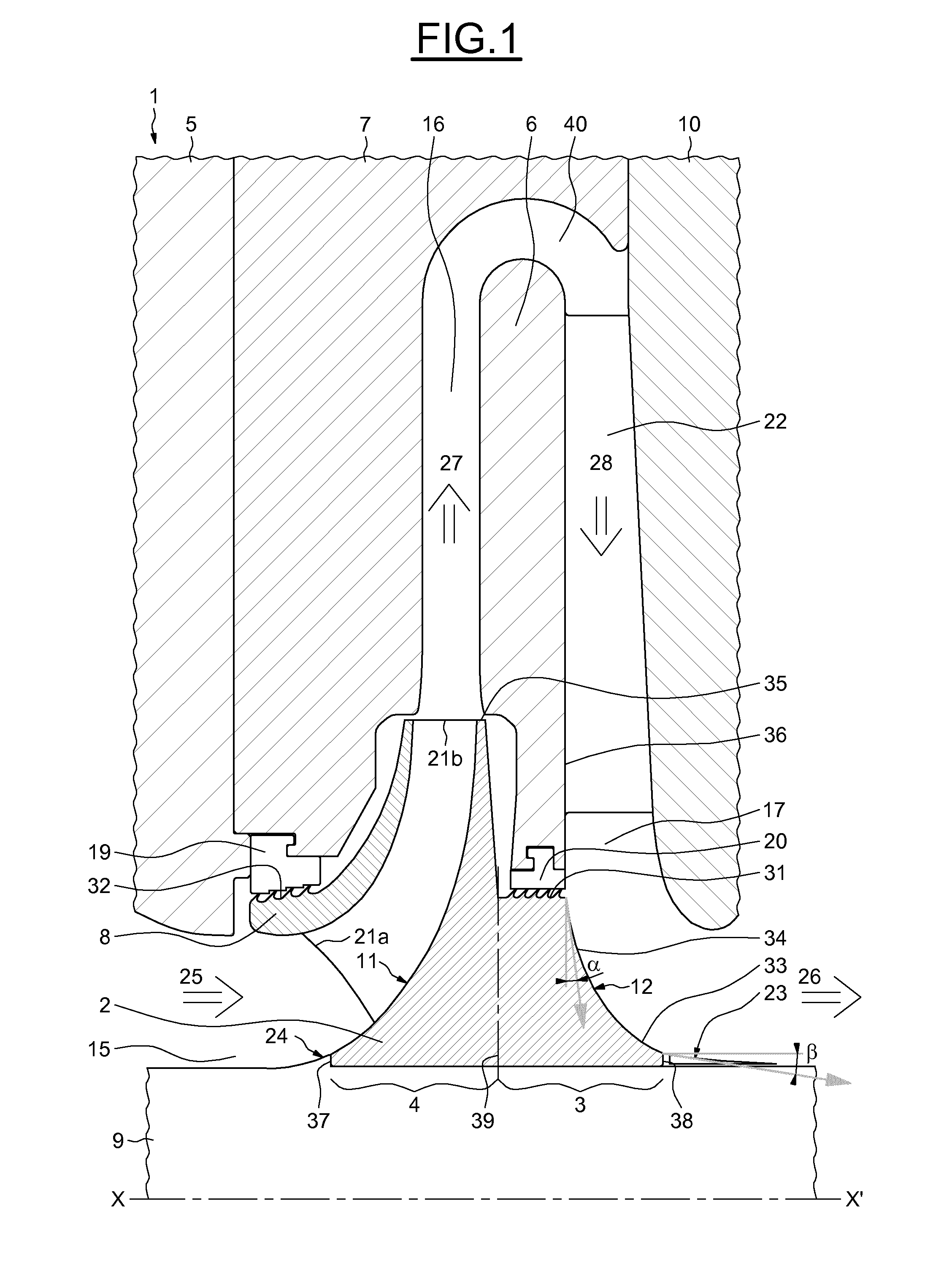
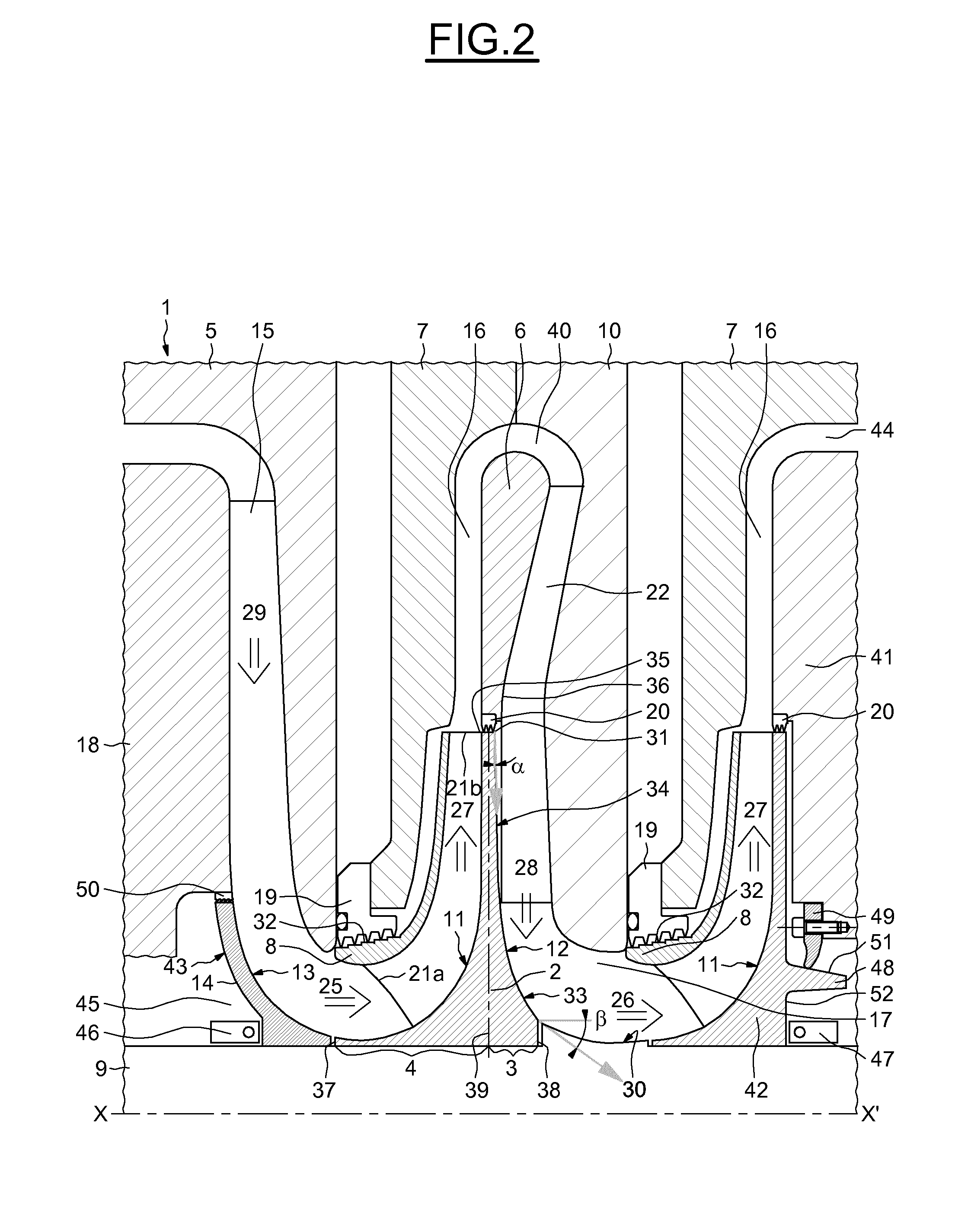
[0058]FIG. 1 shows a portion 1 of a centrifugal compressor according to an embodiment of the invention. The compressor comprises a shaft 9 rotating around an axis X-X′. An impeller wheel 2 is assembled around the shaft 9, so as to rotate around the axis X-X′ together with the shaft 9, and so as to transmit to the shaft axial forces imparted by fluids to the impeller 2. In the description “fluid” or “fluids” refers to the fluids processed by the radial rotating machine.

[0059]In the description, by “radial surface” one means a surface generated by a series of radial lines, i.e. a surface perpendicular to the axis X-X′ of the rotating machine 1.

[0060]By “axial surface”, one means a surface generated by a series of axial lines, i.e. a portion of cylindrical surface with an axis parallel to the axis X-X′.

[0061]The impeller wheel 2 comprises a bladed hub portion 4 and a deflector portion 3, placed downstream of the bladed hub portion 4.

[0062]By downstream one means downstream along the fl...


PUM


Abstract

An impeller wheel assembly for a radial rotating machine, comprises a bladed hub portion of an impeller wheel, with a first radially outward facing, fluid deflecting surface having a curvature profile designed to deflect an axial fluid flow into a radial centrifugal flow, and comprising a deflector portion with a second radially outward facing, fluid deflecting surface. The second radially outward facing surface has a curvature profile designed to deflect a radial centripetal fluid flow into an axial fluid flow.

Description

BACKGROUND[0001]Embodiments of the present invention relate to radial rotating machines, such as centrifugal compressors or single stage fluid expanders.[0002]In general, a radial rotating machine may be a rotating machine for processing a fluid flow, the fluid flow being forced to flow radially at least along part of the flow path.[0003]A radial rotating machine is a rotating machine for processing a fluid flow, in which the fluid flow occurs radially at least along part of the flow path. The radial rotating machine may be for instance a centrifugal compressor.[0004]Centrifugal compressors or single stage expanders are radial rotating machines: they comprise bladed impeller wheels, which are designed to force the fluid flow radially away from the axis of the rotating machine.[0005]These impeller wheels are subjected to axial forces which may be of two types: so-called static axial forces, which are generated by the difference in fluid pressure between the upstream side and the down...

Claims


Application Information

Patent Timeline
IPC IPC(8): F04D29/051F04D29/08F04D29/058F04D29/44F04D29/42F04D29/053F04D17/12F04D29/28
CPCF04D29/051F04D17/12F04D29/083F04D29/058F04D29/441F04D29/4253F04D29/053F04D29/286F04D29/0516F04D29/284
Inventor ALBAN, THOMASGUILLEMIN, SYLVAINBIGI, MANUELEIURISCI, GUISEPPEFALOMI, STEFANO
Owner THERMODYN
Why Eureka
Try Eureka