
Steam generator for nuclear steam supply system

a technology of nuclear steam supply and steam generator, which is applied in the direction of nuclear elements, lighting and heating apparatus, greenhouse gas reduction, etc., can solve the problems of increasing complexity and radiation levels, increasing the number of penetrations into the pressure vessel of the reactor, and affecting the operation of the reactor. , to achieve the effect of preventing fuel failure, reducing fretting damage rate, and preventing rod wastag

Active Publication Date: 2016-07-07
SMR INVENTEC
View PDF3 Cites 19 Cited by
  • Summary
  • Abstract
  • Description
  • Claims
  • Application Information

AI Technical Summary

Benefits of technology

The patent describes a nuclear steam supply system with a deep underground reactor core and a unique design to reduce radiation dose. The system uses a thick-walled reactor vessel made of a material called AME Code to maintain reactor integrity. The system also circulates the primary fluid through the reactor in a gravity-driven manner to reduce the amount of radiation emanating from the containment. This results in a much lower radiation dose compared to traditional pumped-water reactors of a similar size. The system includes a shop fabricated steel containment capable of withstanding a crashing airplane, which is more suitable and economical than a thick concrete containment.

Problems solved by technology

The existing natural circulation PWRs suffer from the drawback that the heat exchange equipment is integrated with and located within the reactor pressure vessel.
Such an arrangement not only makes the heat exchange equipment difficult to repair and / or service, but also subjects the equipment to corrosive conditions and results in increased complexity and a potential increase in the number of penetrations into the reactor pressure vessel.
In addition, locating the heat exchange equipment within the reactor pressure vessel creates problems with respect to radiation levels encountered for crews to repair the heat exchange equipment in proximity to the radioactively hot components of the reactor vessel.

Method used


Image

  • Steam generator for nuclear steam supply system
  • Steam generator for nuclear steam supply system
  • Steam generator for nuclear steam supply system

Examples


Embodiment Construction

[0042]The features and benefits of the invention are illustrated and described herein by reference to exemplary embodiments. This description of exemplary embodiments is intended to be read in connection with the accompanying drawings, which are to be considered part of the entire written description. The disclosure expressly should not be limited to such exemplary embodiments illustrating some possible non-limiting combination of features that may exist alone or in other combinations of features.

[0043]In the description of embodiments disclosed herein, any reference to direction or orientation is merely intended for convenience of description and is not intended in any way to limit the scope of the present invention. Relative terms such as “lower,”“upper,”“horizontal,”“vertical,”, “above,”“below,”“up,”“down,”“top” and “bottom” as well as derivative thereof (e.g., “horizontally,”“downwardly,”“upwardly,” etc.) should be construed to refer to the orientation as then described or as sh...


PUM


Abstract

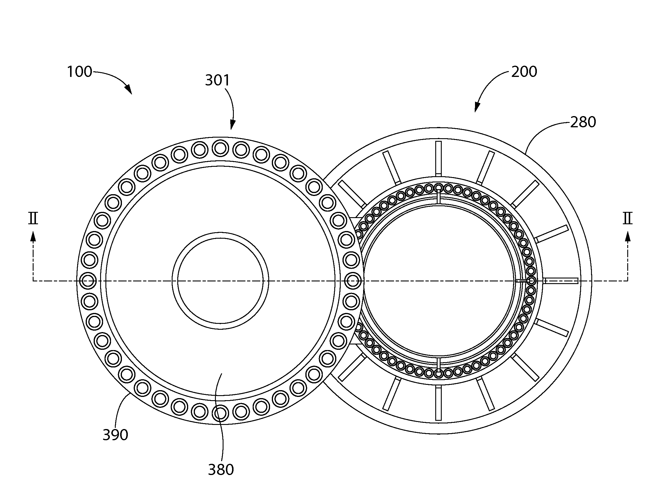
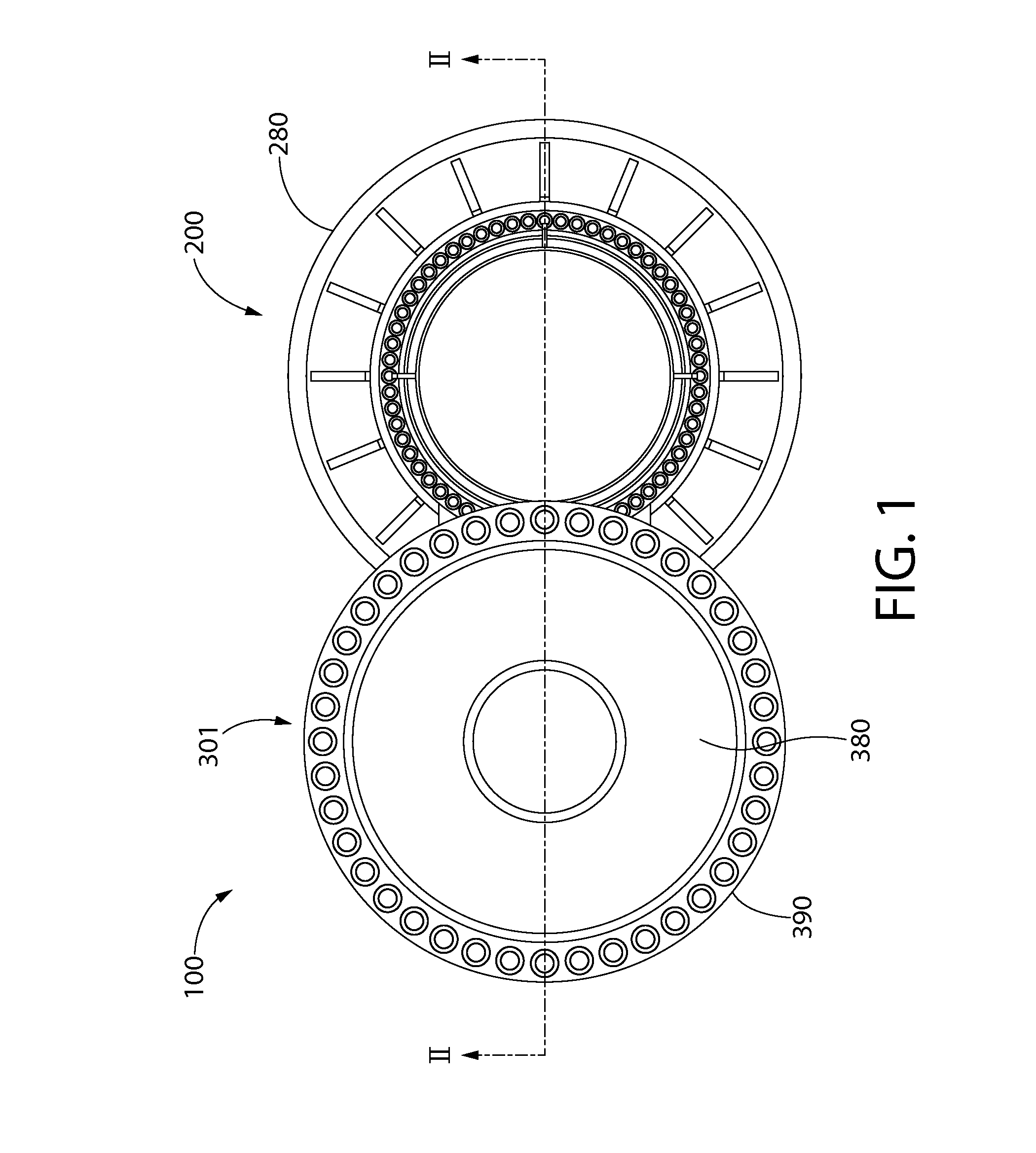
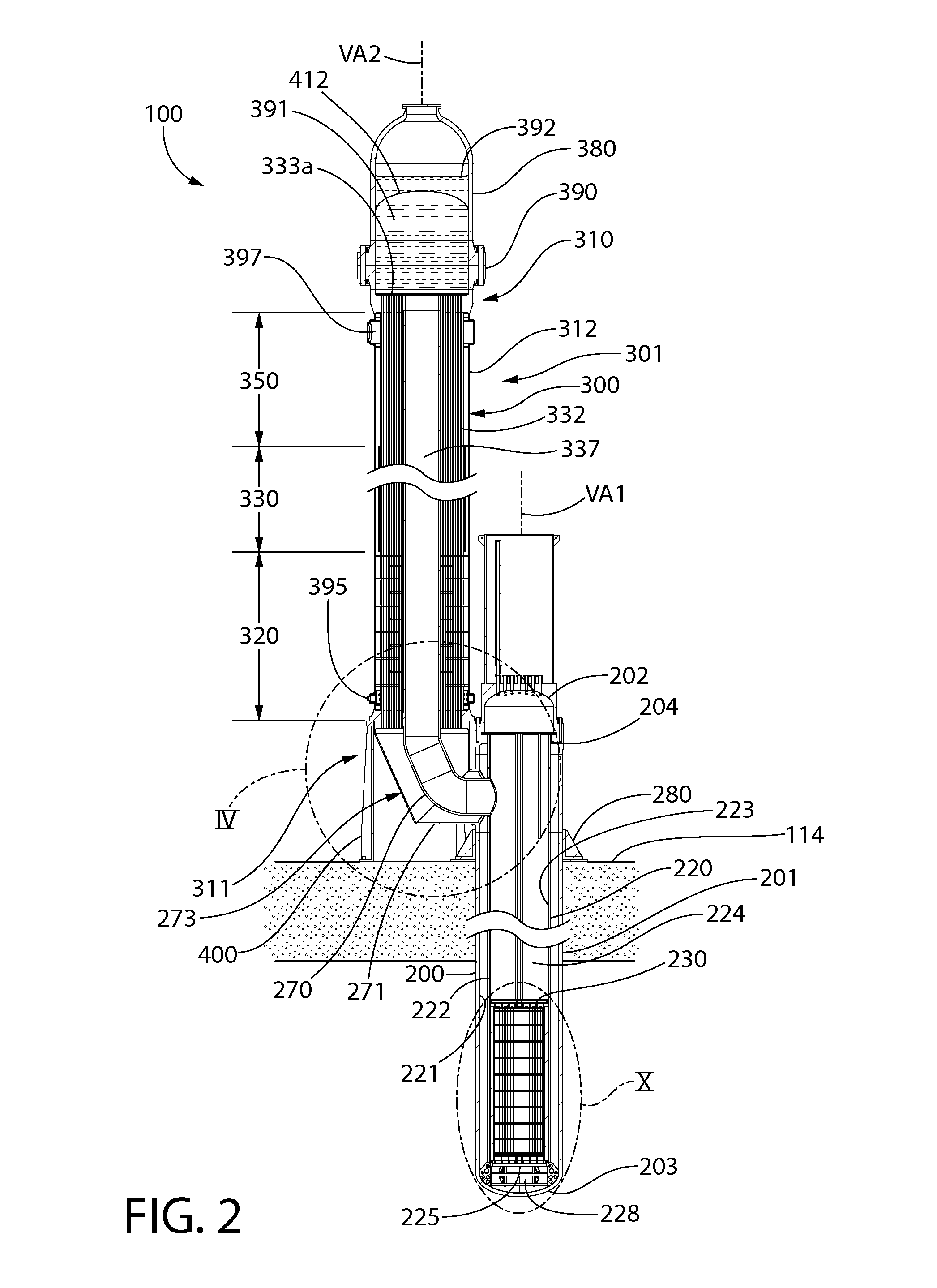
A nuclear steam supply system utilizing gravity-driven natural circulation for primary coolant flow through a fluidly interconnected reactor vessel and a steam generating vessel. In one embodiment, the steam generating vessel includes a plurality of vertically stacked heat exchangers operable to convert a secondary coolant from a saturated liquid to superheated steam by utilizing heat gained by the primary coolant from a nuclear fuel core in the reactor vessel. The secondary coolant, may be working fluid associated with a Rankine power cycle turbine-generator set in some embodiments. The steam generating vessel and reactor vessel may each be comprised of vertically elongated shells, which in one embodiment are arranged in lateral adjacent relationship. In one embodiment, the reactor vessel and steam generating vessel are physically discrete self-supporting structures which may be physically located in the same containment vessel.

Description

CROSS-REFERENCE TO RELATED PATENT APPLICATIONS[0001]The present application claims the benefit of U.S. Provisional Patent Application Ser. No. 61 / 895,267 filed Oct. 24, 2013, the entirety of which is incorporated herein by reference.FIELD OF THE INVENTION[0002]The present invention relates nuclear steam supply systems, and more particularly to a steam generator used in a modular reactor system having natural gravity driven coolant flow circulation.BACKGROUND OF THE INVENTION[0003]Pressurized water reactors (PWRs) for nuclear power generation facilities utilize both pumped and natural circulation of the primary coolant (water) to both cool the reactor core and heat the secondary coolant (water) to produce steam which may be working fluid for a Rankine power generation cycle. The existing natural circulation PWRs suffer from the drawback that the heat exchange equipment is integrated with and located within the reactor pressure vessel. Such an arrangement not only makes the heat excha...

Claims


Application Information

Patent Timeline
IPC IPC(8): G21C15/14G21C15/257
CPCG21C15/257G21C15/14F22B1/023F22B1/026G21C13/032G21C13/04G21C15/18G21C15/22G21C15/26G21D1/006Y02E30/00Y02E30/30F22B37/002F22B37/24
Inventor SINGH, KRISHNA P.RAJKUMAR, JOSEPH
Owner SMR INVENTEC
Learn More