
Method and apparatus for control of pulsed power in hybrid energy storage module

a technology of hybrid energy storage and control method, applied in pulse train generators, pulse techniques, emergency power supply arrangements, etc., can solve problems such as insufficient transmission of large blocks of energy in conventional systems

Active Publication Date: 2016-07-07
RAYTHEON CO
View PDF2 Cites 75 Cited by
  • Summary
  • Abstract
  • Description
  • Claims
  • Application Information

AI Technical Summary

Benefits of technology

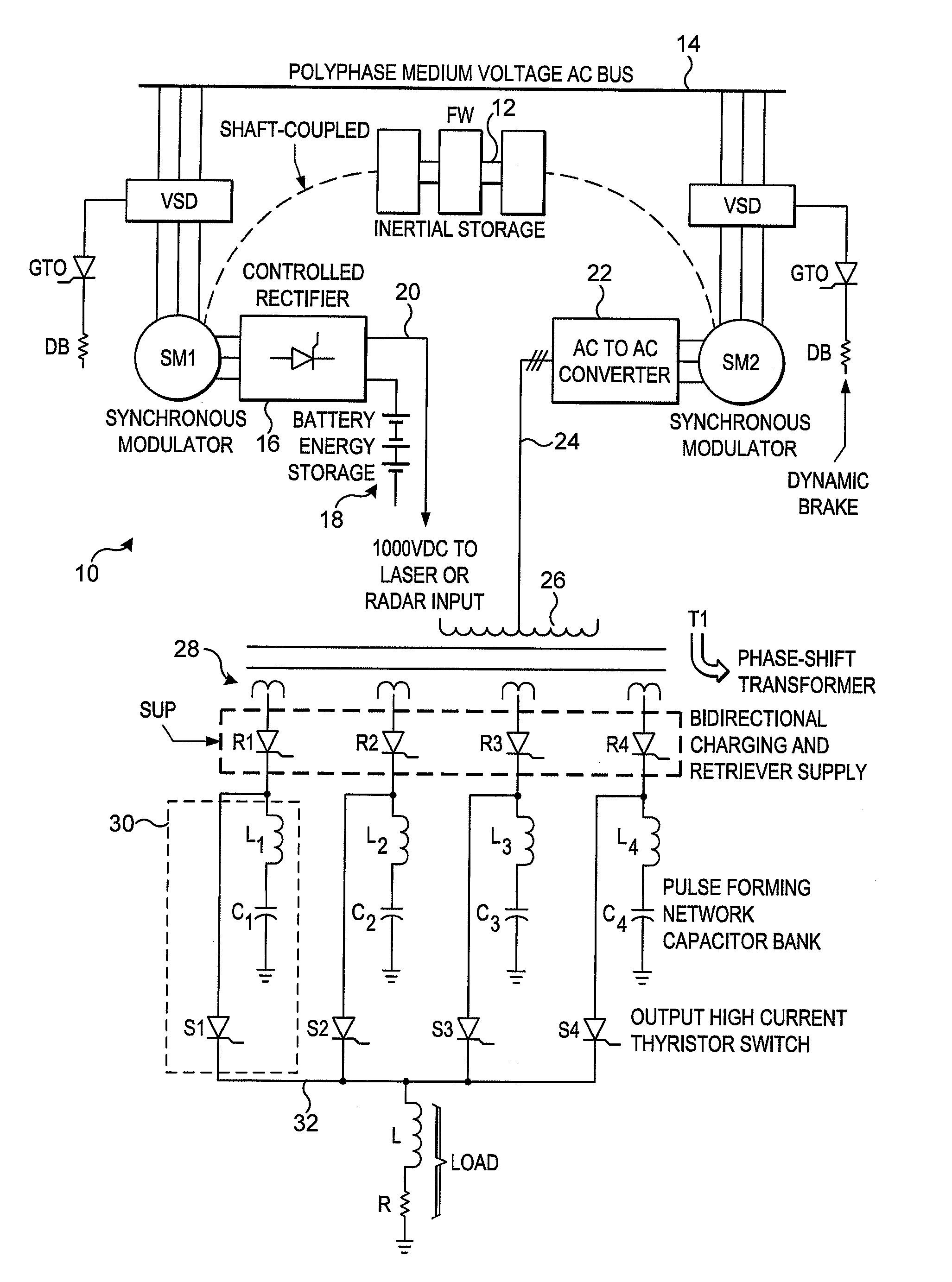
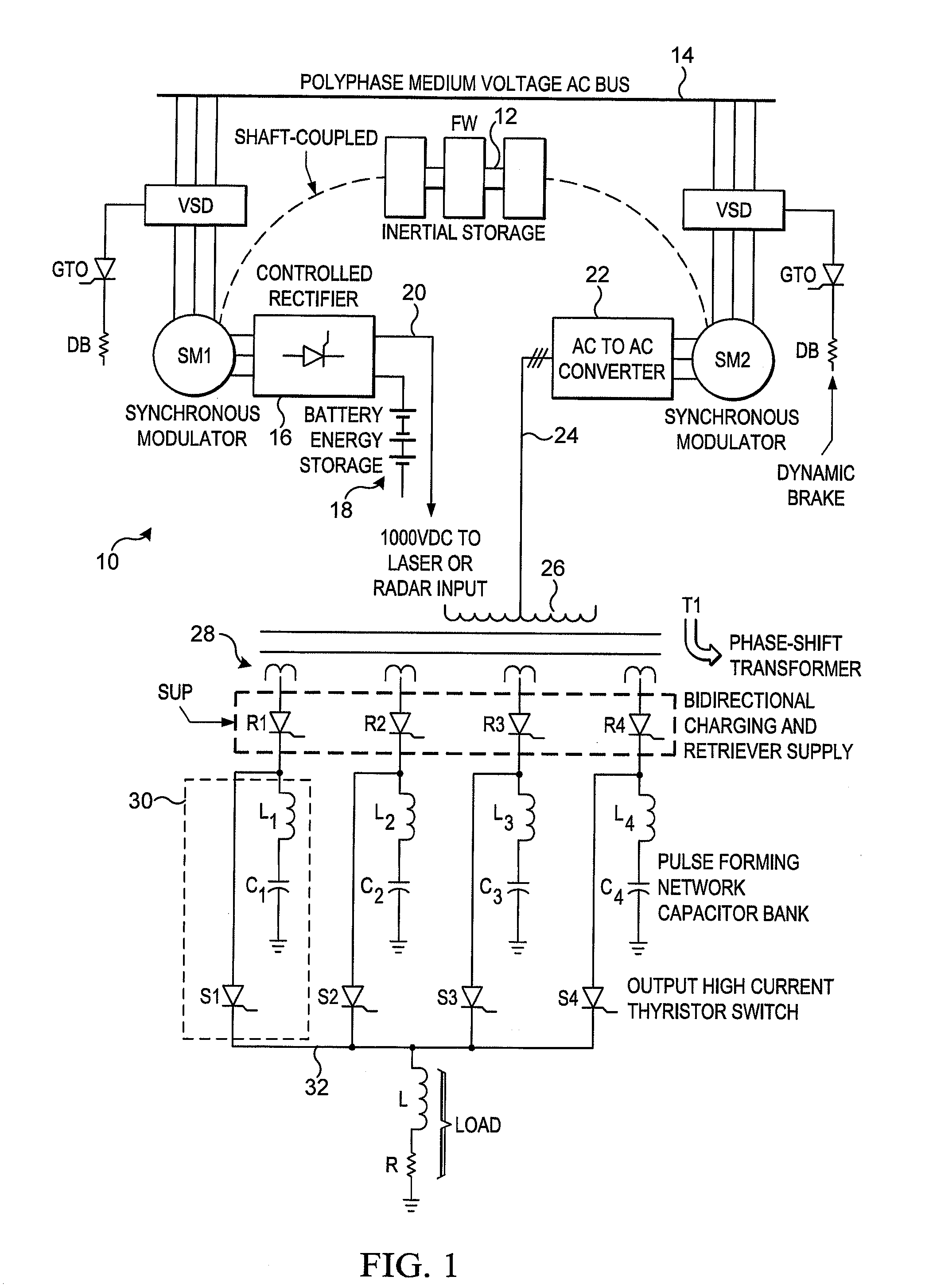
This patent describes a hybrid inertial energy storage system for radar power systems and large pulse forming networks. The system includes an inertial energy storage device and a first dynamo-electric machine directly coupled to the inertial energy storage device. The first machine has multiple input stator windings, a rotor winding, and at least one polyphase output stator winding. The system also includes an electro-chemical battery and a second dynamo-electric machine directly coupled to the flywheel. The second machine has multiple input stator windings, a rotor winding, and at least one polyphase output stator winding. The system is designed to bi-directionally transfer energy between the DC output, the secondary energy storage system, the inertial energy storage device, and the AC source. The technical effects of this patent include improved energy storage and utilization for radar power systems and large pulse forming networks.

Problems solved by technology

Conventional systems are inadequate for transferring large blocks of energy from slow response sources to fast response loads or fast intermediate loads, and recovering energy from pulsed power loads to either intermediate response sources or to an AC source.

Method used


Image

  • Method and apparatus for control of pulsed power in hybrid energy storage module
  • Method and apparatus for control of pulsed power in hybrid energy storage module
  • Method and apparatus for control of pulsed power in hybrid energy storage module

Examples


Embodiment Construction

[0028]It should be understood at the outset that, although example embodiments are illustrated below, the present invention may be implemented using any number of techniques, whether currently known or not. The present invention should in no way be limited to the example implementations, drawings, and techniques illustrated below. Additionally, the drawings are not necessarily drawn to scale.

[0029]This disclosure solves a basic problem of transferring large blocks of energy from slow response sources to fast response loads or fast intermediate loads, and recovering energy from pulsed power loads to either intermediate response sources or to a DC or AC source. Specific embodiments are shown which utilize multiple level DC-to-AC and AC-to-AC input converters on both an active front end and on an output of a resonant converter. The multi-port electrical machinery is fully integrated with an inertial storage unit and an electro-chemical energy storage set with special application to pul...


PUM


Abstract

A hybrid energy storage system is configured to control pulsed power. A first dynamo-electric machine is coupled to an inertial energy storage device and has multiple input stator windings configured to accept input power from a source. A polyphase output stator winding is configured to deliver electric power having a first response time to a DC bus. A secondary energy storage system is coupled to the DC bus and is configured to convert its stored energy to electric power in a bidirectional manner. A second dynamo-electric machine has an input stator winding and at least one polyphase output stator winding coupled to a converter, the converter coupled to a DC output. A polyphase boost exciter is configured to derive energy from the DC bus and excite the second machine input stator winding, wherein the second machine is configured to be excited at a faster rate than the first response time of the first machine.

Description

TECHNICAL FIELD[0001]This disclosure is generally related to pulsed power systems at the megawatt level and gigawatt level, such as those utilized in radar power systems, and more particularly to an inertial energy storage system for radar power systems and large pulse forming network (PFN) charging or operating pulsating loads.BACKGROUND OF THE DISCLOSURE[0002]Large scale energy storage involves several different mechanisms of energy storage which differ in application by how fast and how frequently each subsystem can absorb or deliver energy. Conventional systems are inadequate for transferring large blocks of energy from slow response sources to fast response loads or fast intermediate loads, and recovering energy from pulsed power loads to either intermediate response sources or to an AC source.[0003]Energy storage and pulsed power at the megawatt and gigawatt level require new topologies for the magnetics of the transformer and the electrical machinery, as well as enhanced cool...

Claims


Application Information

Patent Timeline
IPC IPC(8): H03K3/45
CPCH03K3/45H02M7/98H02J1/16H02J5/00Y02E60/16H02J9/066
Inventor KUZNETSOV, STEPHEN
Owner RAYTHEON CO
Learn More