Power storage device and control method thereof

a technology of power storage and power storage device, which is applied in the direction of process and machine control, braking system, instruments, etc., can solve the problems of power-assisted bicycles which are not previously provided with the control function and have difficulty in performing the control function, and achieve the effect of reducing the driving power of motor-driven moving objects

Active Publication Date: 2016-07-14
PANASONIC INTELLECTUAL PROPERTY MANAGEMENT CO LTD
View PDF2 Cites 9 Cited by
  • Summary
  • Abstract
  • Description
  • Claims
  • Application Information

AI Technical Summary

Benefits of technology

[0012]According to the power storage device, it is possible to reduce the driving power of a motor-driven moving object in a particular area by causing a power storage device to perform the control of the present disclosure, even when the motor-driven moving object itself is not previously provided with the function of controlling the driving power in a particular area.

Problems solved by technology

However, power-assisted bicycles which are not previously provided with the control function have difficulty in performing the control function.
This problem is common to power-assisted bicycles, as well as to motor-driven moving objects using storage batteries as driving power sources.

Method used


Image

  • Power storage device and control method thereof
  • Power storage device and control method thereof
  • Power storage device and control method thereof

Examples


first embodiment

[0032]Now, a first embodiment of the present disclosure will be described with reference to the drawings.

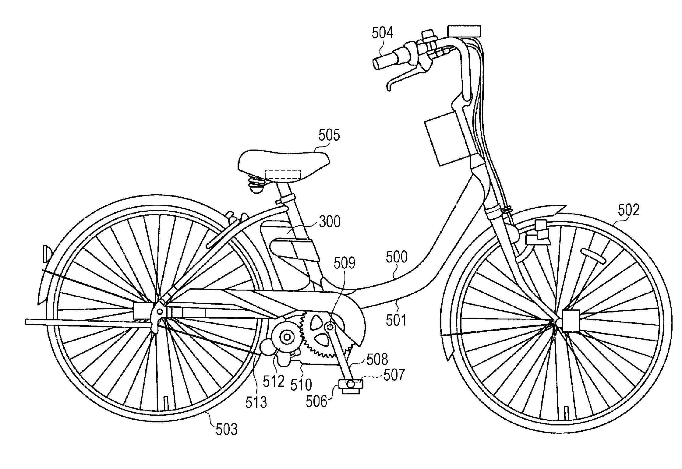
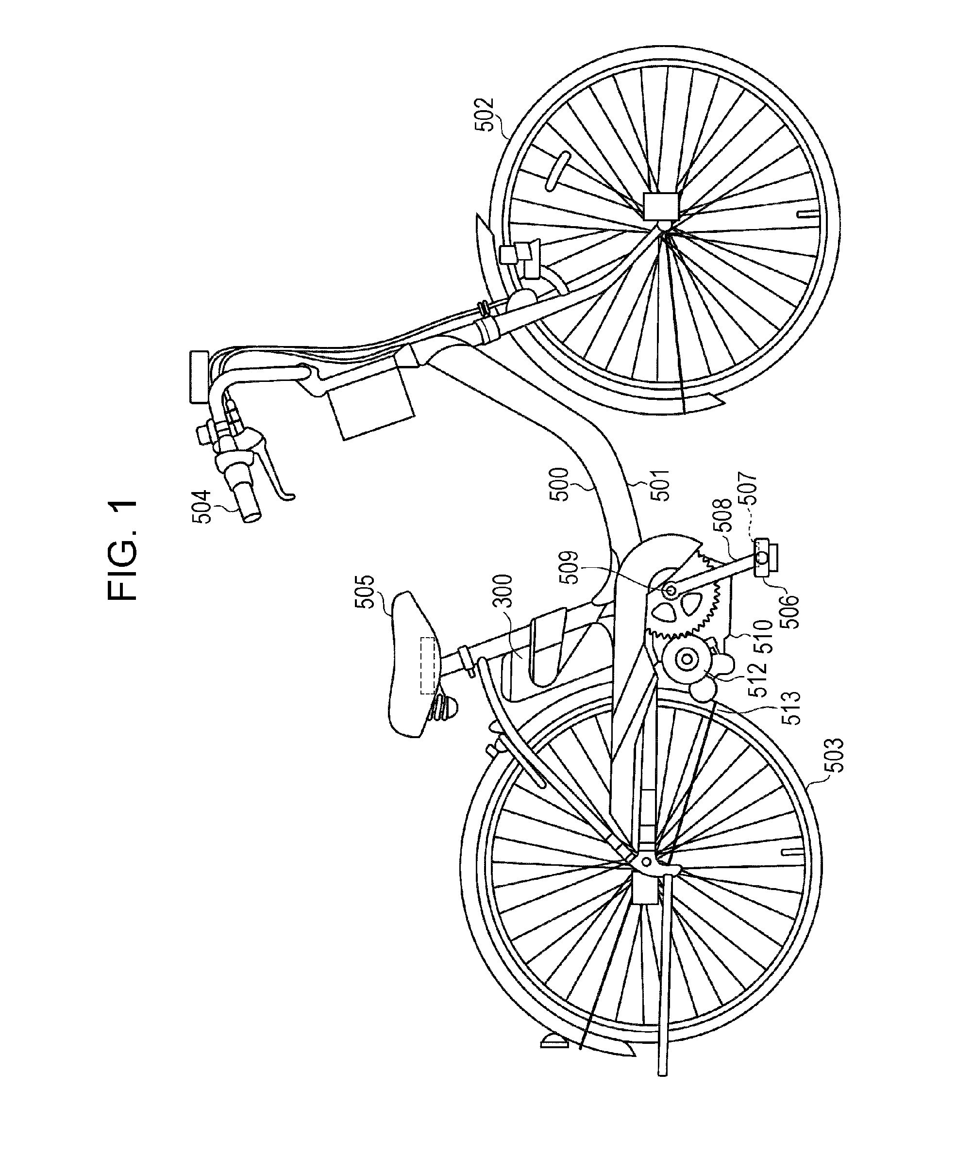
[0033]FIG. 1 is a schematic view of a power-assisted bicycle equipped with a power storage device of a first embodiment.

[0034]A body frame 501 of a power-assisted bicycle 500 has thereon a front wheel 502, a rear wheel 503, a handlebar 504, a saddle 505, a pedal 506, a pedaling force detector 507, a crank arm 508, a crankshaft 509, an assisting power unit 510, and a control unit 511.

[0035]The pedal 506 is connected to the crankshaft 509 through the crank arm 508. The crankshaft 509 is connected to the assisting power unit 510. When the user steps on the pedal 506, the pedaling force is converted into the rotational force of crankshaft 509 through the crank arm 508. The rotational force is transmitted to the assisting power unit 510.

[0036]A power storage device 300 including a storage battery is detachably mounted on a position below the saddle 505, of the body frame 501.

[0037]The...

second embodiment

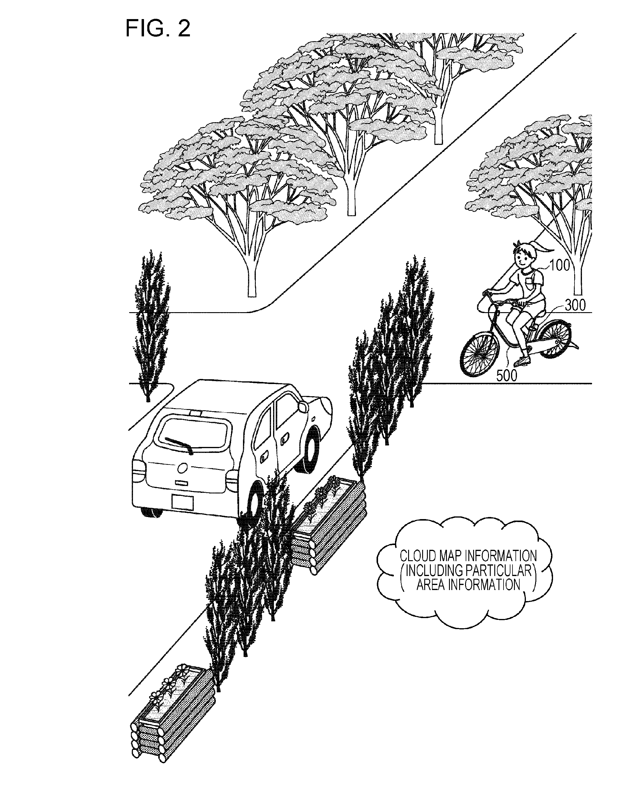
[0125]In the first embodiment, the mobile terminal 100 acquires map information including particular area information from the server in the cloud and repeatedly acquires the location information of the mobile terminal 100 using GPS. The mobile terminal 100 then determines whether the user is driving the power-assisted bicycle 500 within a particular area, on the basis of the particular area information and location information. If it determines that the user is driving in a particular area, the mobile terminal 100 transmits an output power control command signal to the power storage device 300. The power storage device 300 receives the output power control command signal and intermittently outputs the driving power from the storage battery 304 to the motor 512 of the power-assisted bicycle 500.

[0126]In a second embodiment, on the other hand, a mobile terminal 100 acquires map information including particular area information from a server in a cloud and transmits the map informatio...

third embodiment

[0168]A third embodiment does not aim to let the user know that the user is driving a power-assisted bicycle in a particular area, unlike the first and second embodiments, but rather is based on the following problem and object.

[0169]For example, there is a course having a gentle uphill near the starting point and a steep uphill near the destination.

[0170]If the power-assisted bicycle travels such a course while supplying the driving power from the storage battery to the motor on the basis of the pedaling force or the like as is done usually, the power-assisted bicycle may use all the remaining power of the storage battery on the gentle uphill near the starting point in order to drive the motor, depending on the amount of the power remaining in the storage battery (hereafter referred to as “the remaining power amount”). As a result, the user may fail to receive motor-driven assistance on the steep slope near the destination.

[0171]For the user, it would be more appropriate to receive...


PUM


Abstract

A power storage device includes a storage battery, a mounting unit that detachably mounts the power storage device on a motor-driven moving object, an output controller that controls output of driving power from the storage battery to the motor-driven moving object, and a controller that, when the motor-driven moving object is within a particular area, causes the output controller to reduce the driving power supplied from the power storage device to the motor-driven moving object compared to the driving power when the motor-driven moving object is outside the particular area.

Description

BACKGROUND[0001]1. Technical Field[0002]The present disclosure relates to a power storage device including a storage battery and a control method thereof.[0003]2. Description of the Related Art[0004]Storage batteries have been used as the power sources of the motor-driven moving objects, such as power-assisted bicycles.[0005]For example, a power-assisted bicycle uses a storage battery as a power source for driving a motor, detects the pedaling force using a sensor, and controls the power outputted from the storage battery to the motor on the basis of the detection result.[0006]Power-assisted bicycles have been proposed that when the current location thereof falls within an area requiring caution or when the distance between the power-assisted bicycle and another vehicle falls within a predetermined distance, cause an assisting drive controller to change the assisting drive force for assisting the pedaling force and to give an alarm (e.g., Japanese Unexamined Patent Application Publi...

Claims


Application Information

Patent Timeline
Patent Type & Authority Applications(United States)
IPC IPC(8): B62M6/45B62M6/90B60L15/08G05D1/00
CPCB62M6/45B60L15/08B62M6/90G05D1/0022B60L2200/12B60L2240/622B60L2240/68B60L2240/70B60L2250/16B60L2250/26B60L2260/54Y02T90/16B60L50/20H01M10/4257Y02T10/72Y02E60/10Y02T10/70
Inventor TOYA, SHOICHI
Owner PANASONIC INTELLECTUAL PROPERTY MANAGEMENT CO LTD
Why Eureka
Try Eureka