
Thermal radiation shield for superconducting magnet, superconducting magnet and magnetic resonance imaging device

a superconducting magnet and radiation shield technology, applied in the field of low temperature superconducting technology, can solve the problems of complex processing, high time cost and process cost of thermal radiation shield, and achieve the effect of saving process cost and time cos

Active Publication Date: 2016-07-14
SIEMENS SHENZHEN MAGNETIC RESONANCE
View PDF4 Cites 7 Cited by
  • Summary
  • Abstract
  • Description
  • Claims
  • Application Information

AI Technical Summary

Benefits of technology

The invention provides an annular end cap for a thermal radiation shield that has a toothed structure, instead of a decorative border structure. This simplifies the manufacturing process and reduces costs by avoiding complex punching and spinning. The technical effect is an improved manufacturing efficiency and cost savings.

Problems solved by technology

However, shaping of the decorative border structure requires the use of punching, spinning and similar processes, and when shaping is complete, it is still necessary to perform additional machining processes such as milling, thus the processing is complex, and the time costs and process costs of the thermal radiation shield are high.

Method used


Image

  • Thermal radiation shield for superconducting magnet, superconducting magnet and magnetic resonance imaging device
  • Thermal radiation shield for superconducting magnet, superconducting magnet and magnetic resonance imaging device
  • Thermal radiation shield for superconducting magnet, superconducting magnet and magnetic resonance imaging device

Examples


Embodiment Construction

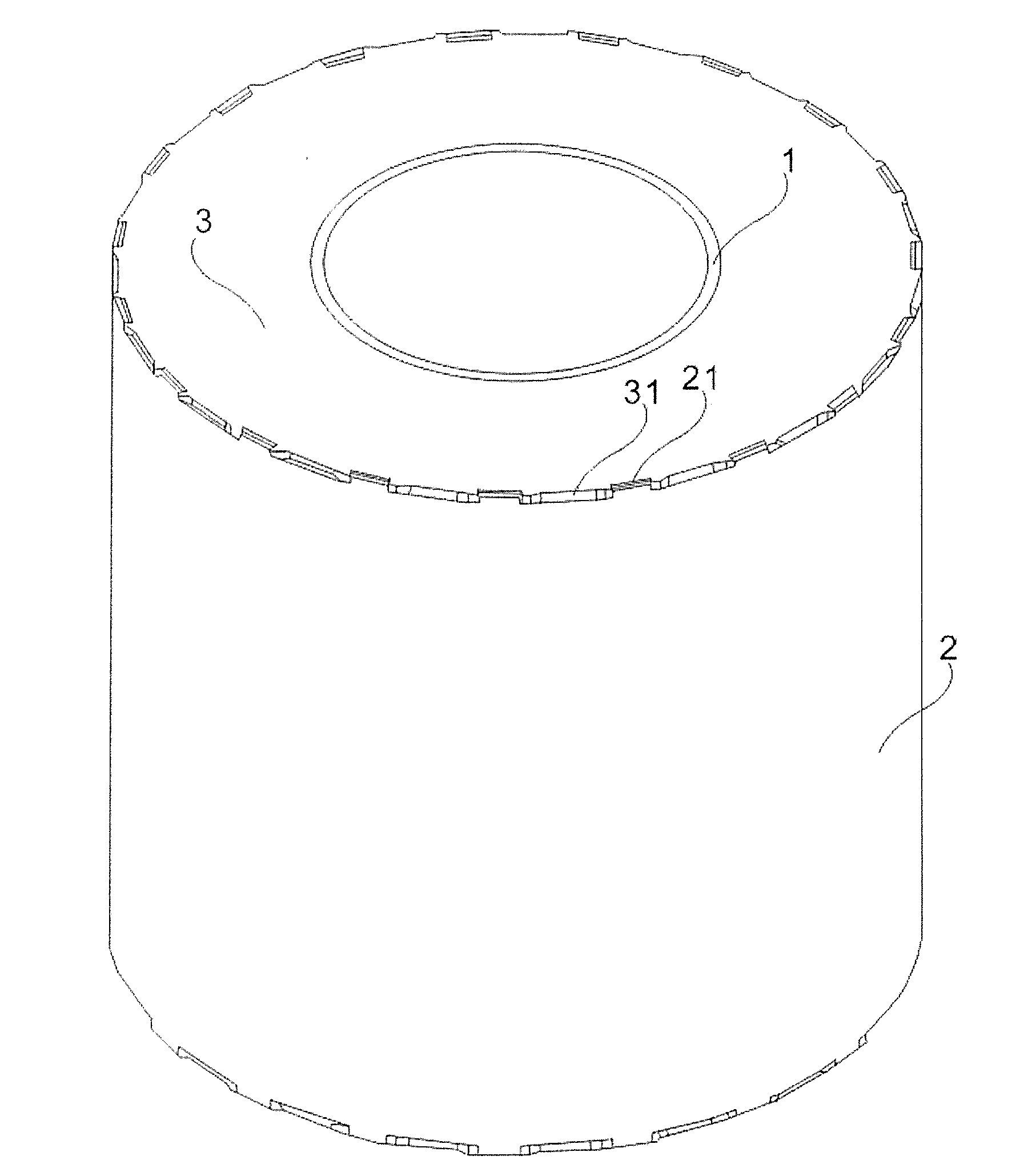
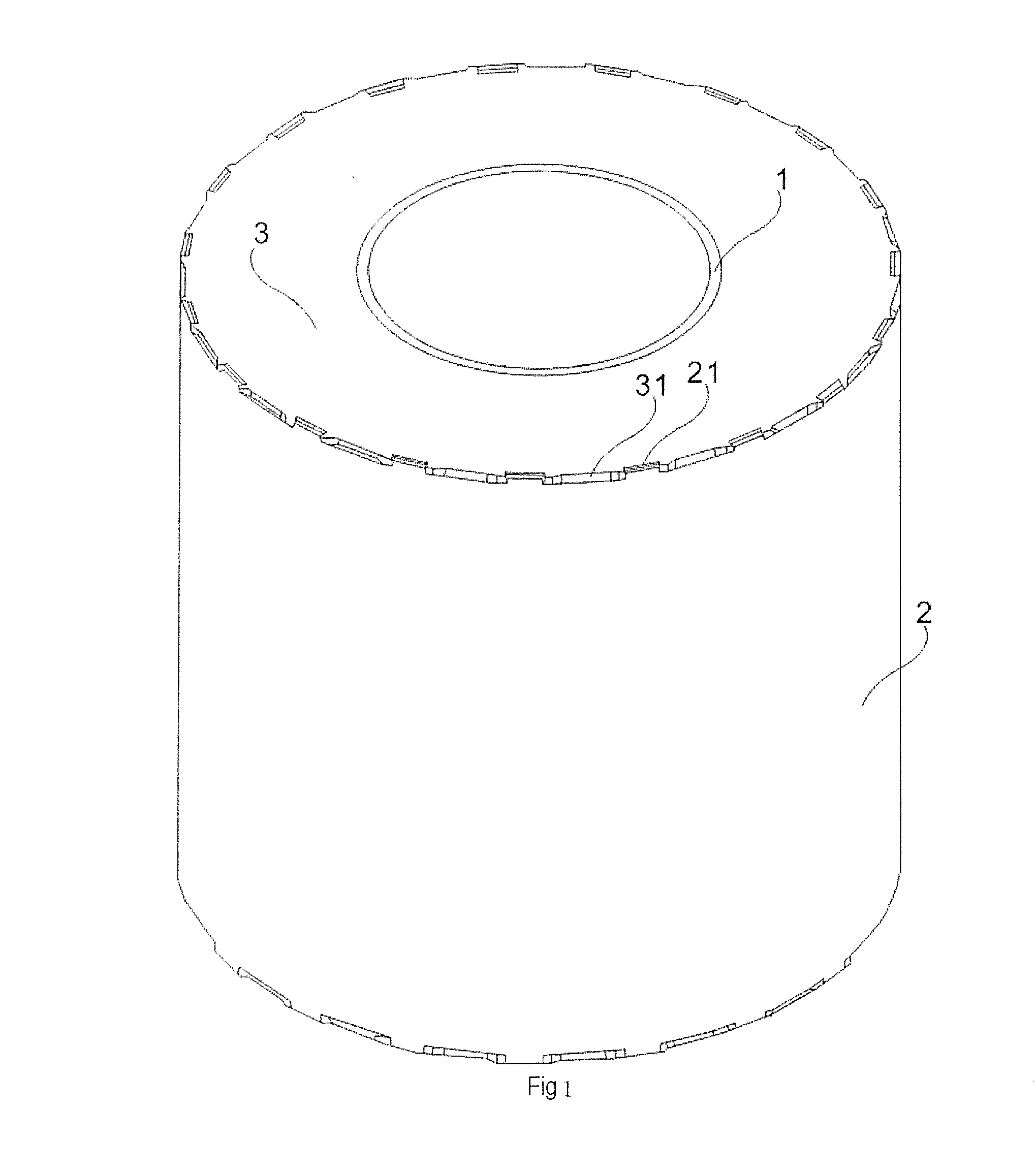
[0024]FIG. 1 schematically shows a thermal radiation shield for a superconducting magnet provided in an embodiment of the present invention, having an inner tube 1, an outer tube 2 and an annular end cap 3.

[0025]The outer tube 2 is arranged around the periphery of the inner tube 1; specifically, both the outer tube 2 and the inner tube 1 are cylindrical, and the diameter of the outer tube 2 is greater than the diameter of the inner tube 1, so that the outer tube 2 can be arranged around the periphery of the inner tube 1. Generally, in order to obtain better heat conduction performance, the outer tube 2 can be made by processing aluminum metal, so that the mechanical performance of the outer tube 2 is poor, in other words, the material of the outer tube 2 is soft, and readily deforms under the action of external forces.

[0026]Since the outer tube 2 is readily acted on by external forces such as electromagnetic forces during use, and the mechanical performance of the outer tube 2 is po...


PUM

PropertyMeasurementUnit
superconductingaaaaaaaaaa
widthaaaaaaaaaa
magneticaaaaaaaaaa

Abstract

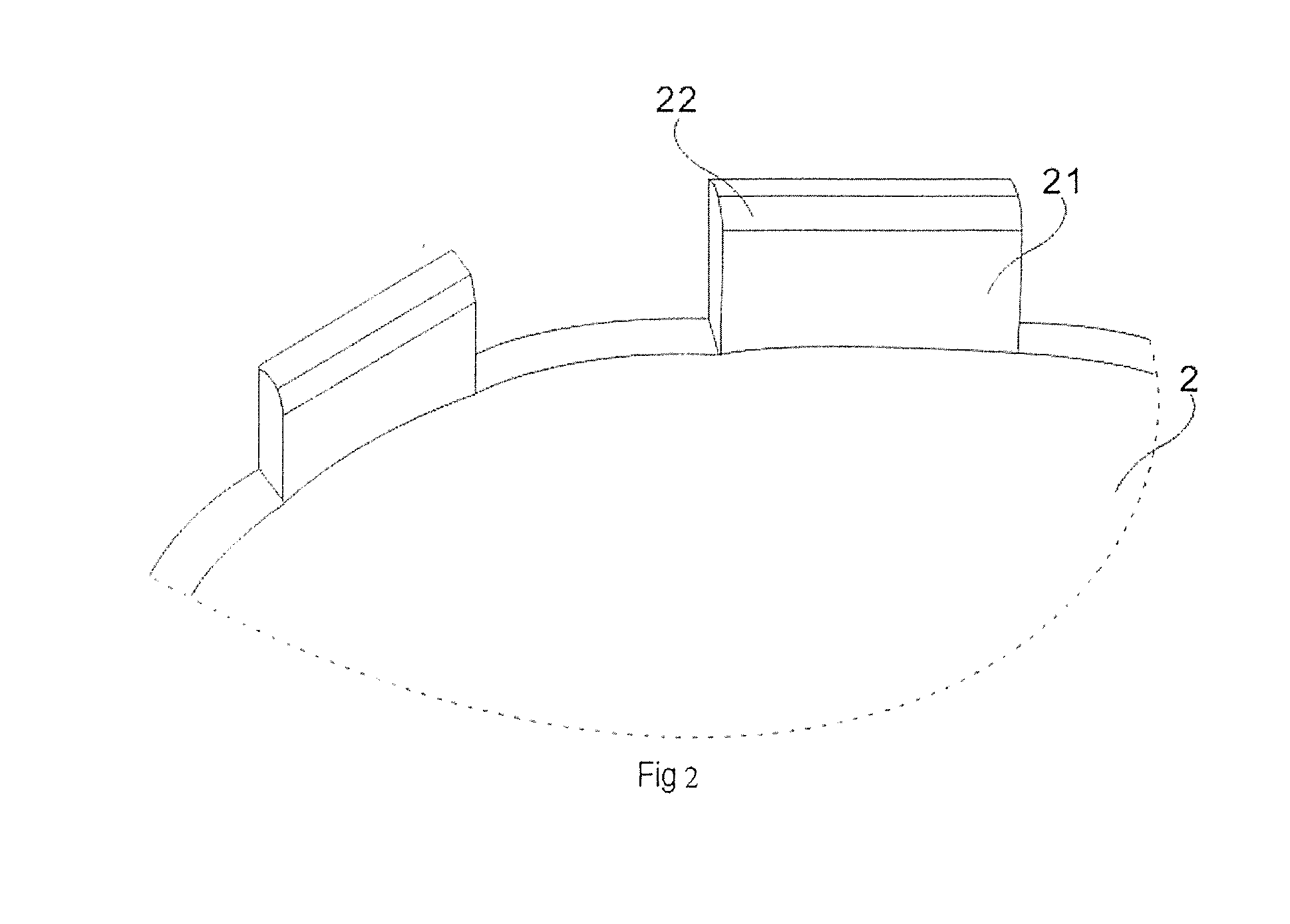
A thermal radiation shield for a superconducting magnet has an inner tube, an outer tube arranged around the periphery of the inner tube, and an annular end cap disposed therebetween, and connected in a fixed manner to an edge of the inner tube by an inner edge of the annular end cap. A first toothed part is formed at an outer edge of the annular end cap, the first toothed part being connected by meshing with a second toothed part formed by an edge of the outer tube. The annular end cap with a toothed structure allows only a simple cutting process on raw material to be performed in order to obtain the annular end cap and the first toothed part formed at the outer edge thereof, thereby avoiding complex punching, spinning and similar processes, and saving production costs.

Description

BACKGROUND OF THE INVENTION[0001]1. Field of the Invention[0002]The present invention concerns low-temperature superconducting technology, in particular a thermal radiation shield for a superconducting magnet, and a superconducting magnet and a magnetic resonance imaging apparatus with such a shield.[0003]2. Description of the Prior Art[0004]In superconductive magnetic resonance imaging (MRI), selected dipoles in a subject are excited and a magnetic resonance signal emitted by the dipoles is received, so as to generate an image based on the magnetic resonance signal. To encourage excitation of the selected dipoles in the subject, a strong uniform magnetic field is needed. The strong uniform magnetic field can be generated by a superconducting magnet coil operating at low temperature. To thermally isolate the superconducting magnet coil, and protect it from interference from heat in forms such as conduction, convection and radiation in the surrounding environment, the superconducting...

Claims


Application Information

Patent Timeline
Patent Type & Authority Applications(United States)
IPC IPC(8): G01R33/38H01F6/00G01R33/3815
CPCG01R33/3804H01F6/00G01R33/3815H01F6/04
Inventor HUANG, LI KAIKERSHAW, EDWARD WEDDERBURNMANN, NICHOLASXIU, HAI TAOZHANG, BU QING
Owner SIEMENS SHENZHEN MAGNETIC RESONANCE
Learn More