Combustion furnace

Active Publication Date: 2016-07-21
NAT CHUNG SHAN INST SCI & TECH
View PDF19 Cites 6 Cited by
  • Summary
  • Abstract
  • Description
  • Claims
  • Application Information

AI Technical Summary

Benefits of technology

[0029]Accordingly, the first air holes allow the swirl generation when the fresh air enters into the inner shell, so that the gas inside the combustion furnace can flow fluently, the flame in the combustion furnace can be retarded from moving upwardly, and the temperature inside the combustion furnace can be maintained to improve the combustion performance of the combustion furnace. Additionally, the inlet gas hole at the

Problems solved by technology

However, conventionally, due to insufficient air in the combustion furnace, the ignition time may be too long to allow the materials inside the combustion furnace to ignite.
Additionally, when larger sized materials are placed in the combustion furnace during combustion, the flame in the combustion furnace prevents complete combustion, and generates a considerable volume of black smoke and carbon monoxide, while combustion performance is poor.
Conventionally, s

Method used


Image

  • Combustion furnace
  • Combustion furnace
  • Combustion furnace

Examples


first embodiment

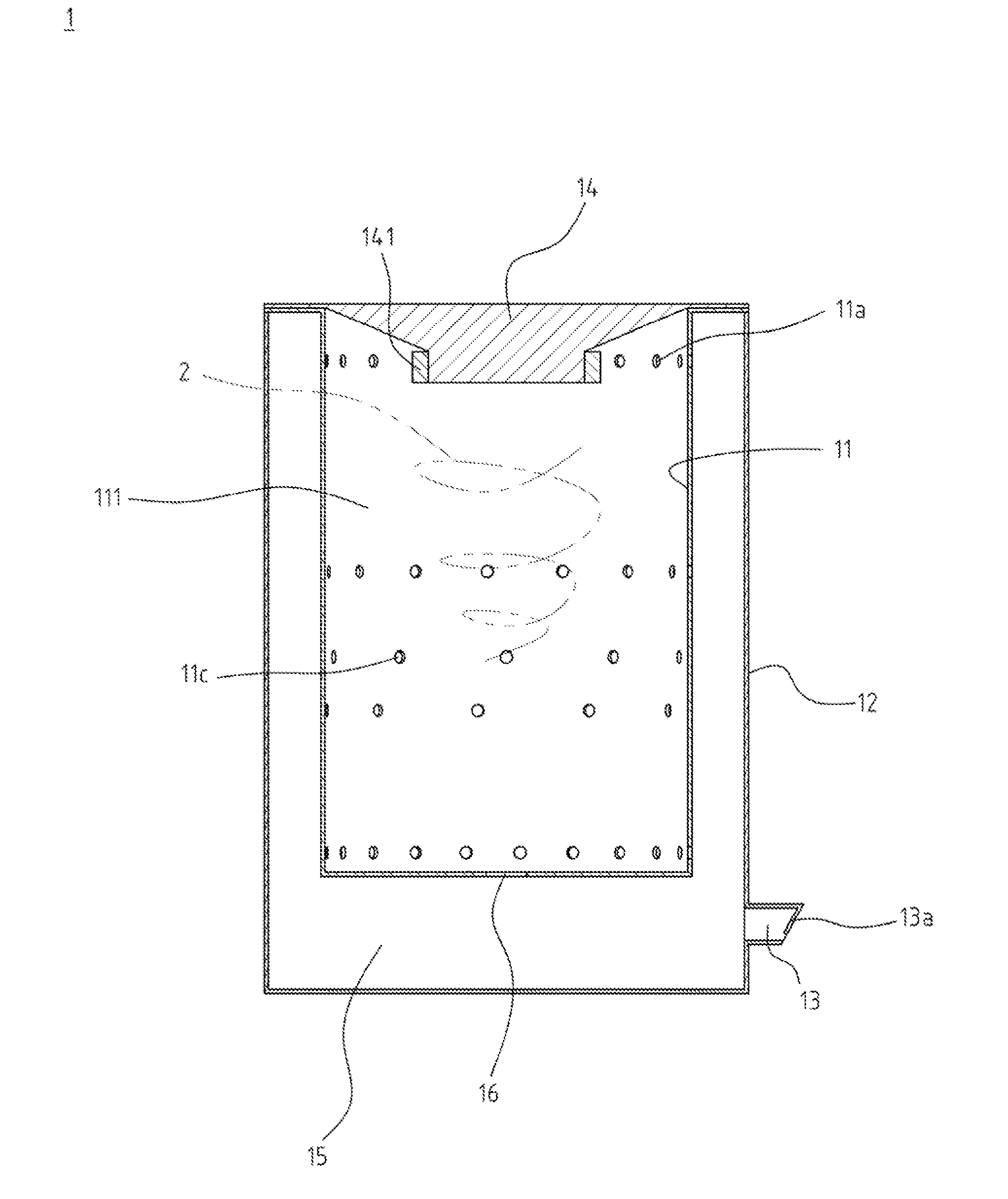
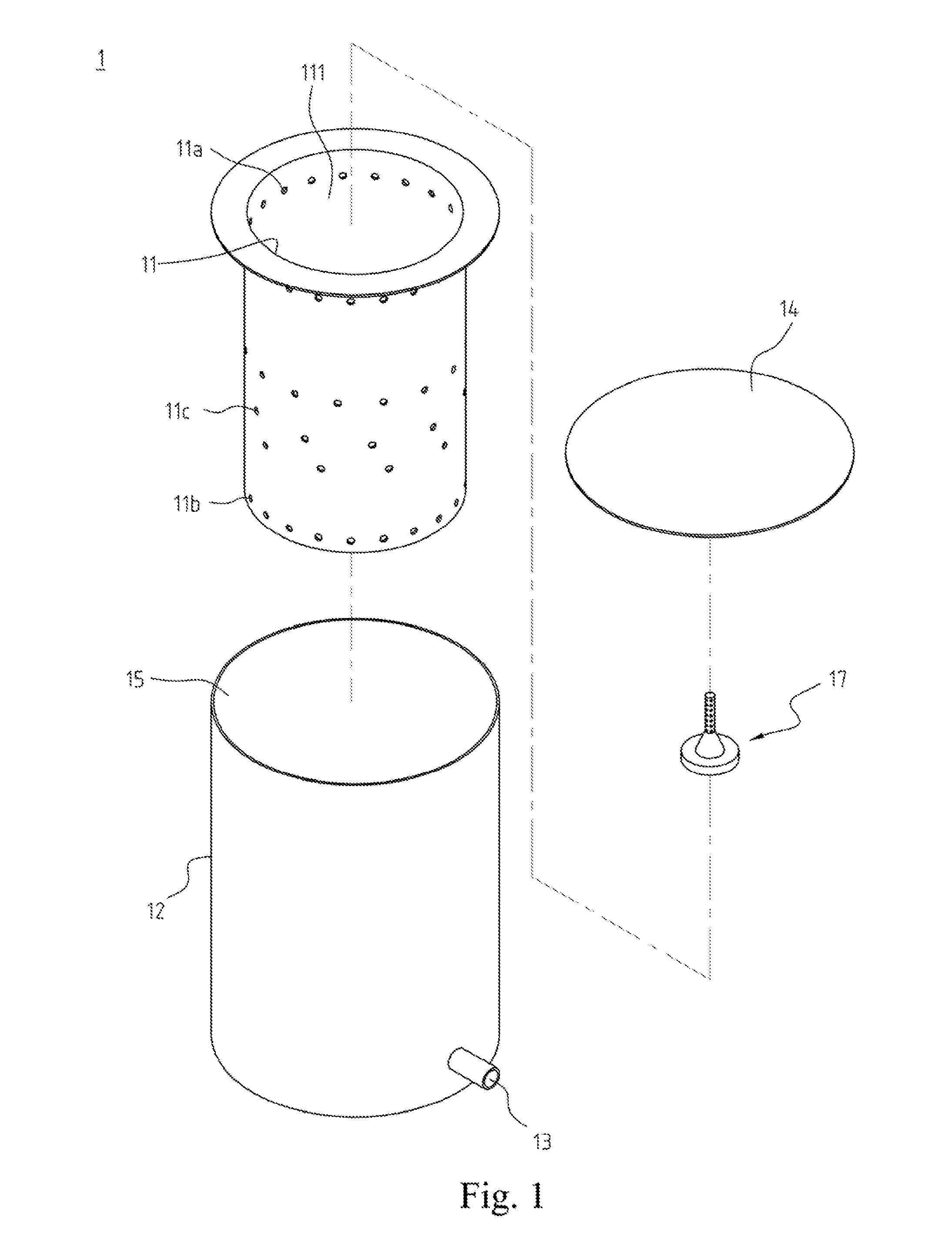
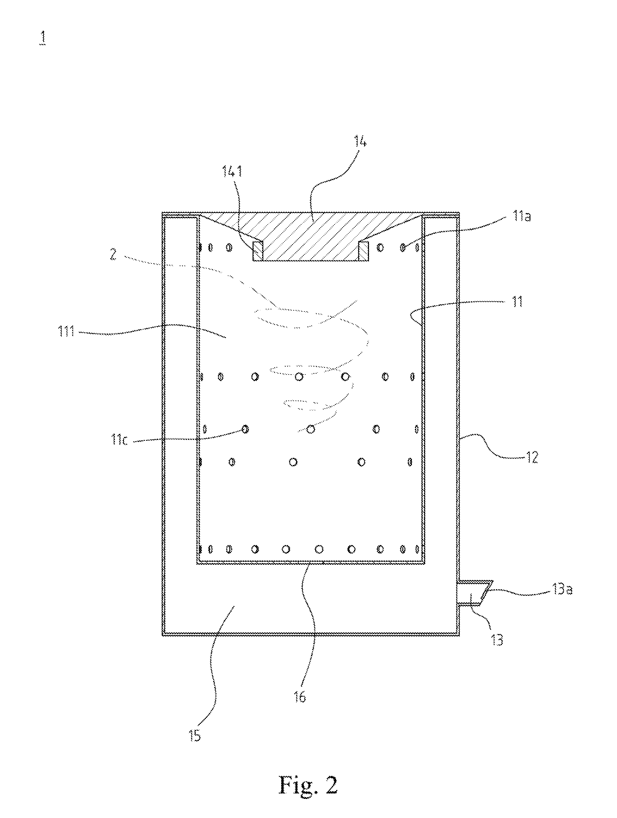
[0040]Please refer to FIG. 1, illustrating an exploded view of a combustion furnace 1 according to the present invention. The combustion furnace 1 comprises an inner shell 11, an outer shell 12, a gas inlet piping 13 and a flame inhibiting cover 14. The inner shell 11 defines a receiving cavity 111 therein. The inner shell 11 defines a plurality of first gas holes 11a around the periphery of a top portion thereof. The inner shell 11 defines a gas inlet hole 16 at a bottom thereof. The outer shell 12 encloses the inner shell 11 such that a gas flowing space 15 is defined between the inner shell 11 and the outer shell 12. The diameter of the inner shell 11 may be, but not limited to, in the range from 40 cm to 70 cm. The depth of the inner shell 11 may be, but not limited to, in the range from 60 cm to 130 cm. The diameter of the outer shell 12 may be, but not limited to, in the range from 42 cm to 75 cm. The gas inlet piping 13 has an opening formed at one end thereof, and the gas in...

fourth embodiment

[0048]Please refer to FIG. 6, illustrating a sectional view of the combustion furnace 1 according to the present invention. The combustion furnace 1 further comprises a combustion supporting device 17 in the receiving cavity 111 and above the gas inlet hole 16. The combustion supporting device 17 comprises a tubular member 171, a cone-shaped member 172 and a base portion 173. The cone-shaped member 172 defines an inserting groove 1721 therein, such that a bottom of the tubular member 171 is received in the inserting groove 1721, as shown in FIG. 5. The base portion 173 is connected to a bottom of the cone-shaped member 172. The tubular member 171 further defines a plurality of vents 1711 around a top portion thereof.

[0049]Powdered ceramic materials can be placed into the space defined by the outer surface of the lower portion of the tubular member 171 and an inner wall of the cone-shaped member 172 to maintain the temperature of the combustion furnace 1, and ensure stable combustion...


PUM


Abstract

A combustion furnace includes an inner shell, an outer shell, a gas inlet piping and a flame inhibiting cover. The inner shell defines a receiving cavity therein. The inner shell defines a plurality of first gas holes around the periphery of a top portion thereof. The inner shell defines a gas inlet hole at a bottom thereof. The outer shell encloses the inner shell such that a gas flowing space is defined between the inner shell and the outer shell. The gas inlet piping has an opening formed at one end thereof, and the gas inlet piping communicates with the gas flowing space. The flame inhibiting cover is atop the outer shell and the inner shell, and a lower flange of the flame inhibiting cover is below the first gas holes.

Description

BACKGROUND OF THE INVENTION[0001]1. Field of the Invention[0002]The present invention relates to a combustion furnace, in particular, to a combustion furnace in which the temperature inside the combustion furnace can be maintained to achieve better combustion efficiency.[0003]2. The Prior Arts[0004]Combustion furnaces burn combustible materials, such as woods, leaves, papers, charcoals or other biomass fuels, so combustion furnaces can be provided to cook or to generate heat. Conventionally, a combustion furnace includes an inner shell and an outer shell. The inner shell is provided as the space for the combustion. Combustion furnaces are provided as heat providers for families. In addition to large combustion furnaces used in households or industries, combustion furnaces are also suitable for outdoor activities, and the volume and weight of combustion furnaces has gradually been reduced to allow for personal combustion furnaces.[0005]However, conventionally, due to insufficient air...

Claims


Application Information

Patent Timeline
IPC IPC(8): F24B5/02F24B7/00F23M9/04
CPCF24B5/023F24B7/005F23M9/04F23M9/02F23G5/42F24B1/202F24B5/021
Inventor GAO, CHUNG-HSINGHSIEN, HSUN-MINGWENG, ZONG-YIKUO, YANN-LONG
Owner NAT CHUNG SHAN INST SCI & TECH
Why Eureka
Try Eureka