High-current plug-in connection with multi-arm contact lamellae

a multi-arm contact and plug-in technology, applied in the direction of coupling contact members, coupling device connections, electrical apparatus, etc., can solve the problems of low electrical resistance, high service life, and often imposed, and achieve good electrical contact, reduce the surface wear of contact pins, and increase the overall length of the contacting system

Active Publication Date: 2016-07-21
ROBERT BOSCH GMBH
View PDF3 Cites 9 Cited by
  • Summary
  • Abstract
  • Description
  • Claims
  • Application Information

AI Technical Summary

Benefits of technology

[0015]In one exemplary embodiment, the contact lamellae and / or the arm have / has bulges in the radial direction of the contacting system which are designed for contacting the contact pin or the contact sleeve in each case. The advantage of the bulges may be a plurality of defined contact points which delimit, among other things, a length of the current paths across the contact lamellae. In one example, the contact lamellae together with the bulges are made of a spring steel, and may thus allow an elastic deflection in the radial direction. Bulges may have a corrugated profile or other suitable profiles in their longitudinal section in parallel to a longitudinal axis of the contact sleeve.
[0016]In one exemplary embodiment, the spatial arrangement of the contact lamellae and of the arm and a spatial arrangement of the bulges are designed in such a way that bulge maxima of adjacent contact lamellae in the circumferential direction of the contact sleeve are offset with respect to one another, or that bulge maxima of adjacent contact lamellae are offset with respect to one another or situated spaced apart from one another along the circumference of this projection of the contact sleeve, in an axial projection on a plane which is orthogonal with respect to the longitudinal axis. This may have the advantage that the contact points on the contact pin are distributed more uniformly across the circumference. In other words, multiple contact points may be prevented from simultaneously sliding along the same surface line, extending in the axial direction of the contact sleeve, when the contact pin is inserted. For example, abrasive wear on the surface of the contact pin may be reduced in this way.
[0017]In one exemplary embodiment, the contacting system is designed in such a way that the bulges of the contact lamella elastically deflect when a deflection force is applied in the direction of the inner wall of the contact sleeve, thus increasing an overall length of the contacting system. One advantage may be considered to be that an elastic deflection may allow locking of the contact pin in the contact sleeve, and in addition good electrical contacting may be achieved due to the contact force that is generated.
[0018]Due to the radial movement, partial areas of the contact lamella are shifted in the axial direction along the inner wall of the contact sleeve or along a surface of the contact pin. An overall length of the contacting system is increased in this way.
[0019]In one specific embodiment of the present invention, the contacting system is connected to the contact sleeve at one of the collars. A defined position of the contacting system within the contact sleeve as well as additional electrical contacting between the contacting system and a collar and / or between the contacting system and the contact sleeve may be achieved in this way. This connection may also be used to prevent the contacting system from sliding out of the inner area of the contact sleeve when the contact pin is not inserted. For example, the collar may be connected to the contact sleeve via a weld spot.
[0020]In one specific embodiment of the present invention, the collar situated at one end-face side of the contact sleeve has a protrusion which projects beyond an edge of the contact sleeve on the end-face side, for example beyond the edge in the radial direction, and overlaps or encompasses same, for example, so that moving of the contacting system into the contact sleeve is limited. This may have the advantage that when a contact pin is inserted into the cross section of the contact sleeve the friction with the contacting system created thereby prevents the contacting system from being pushed undesirably far into an interior of the contact sleeve. Due to the protrusion, the end-face side of the contact sleeve may be utilized as a retaining surface. In one example, a protrusion is permanently fastened to the end face of the contact sleeve with the aid of a weld spot, for example.

Problems solved by technology

In particular when connecting elements and contact elements are used, various requirements for secure contacting, and at the same time low electrical resistance and high service life, are often imposed.

Method used


Image

  • High-current plug-in connection with multi-arm contact lamellae
  • High-current plug-in connection with multi-arm contact lamellae
  • High-current plug-in connection with multi-arm contact lamellae

Examples


Embodiment Construction

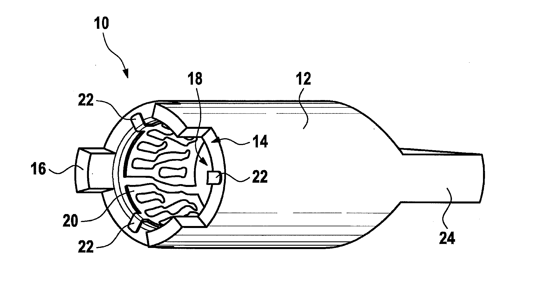
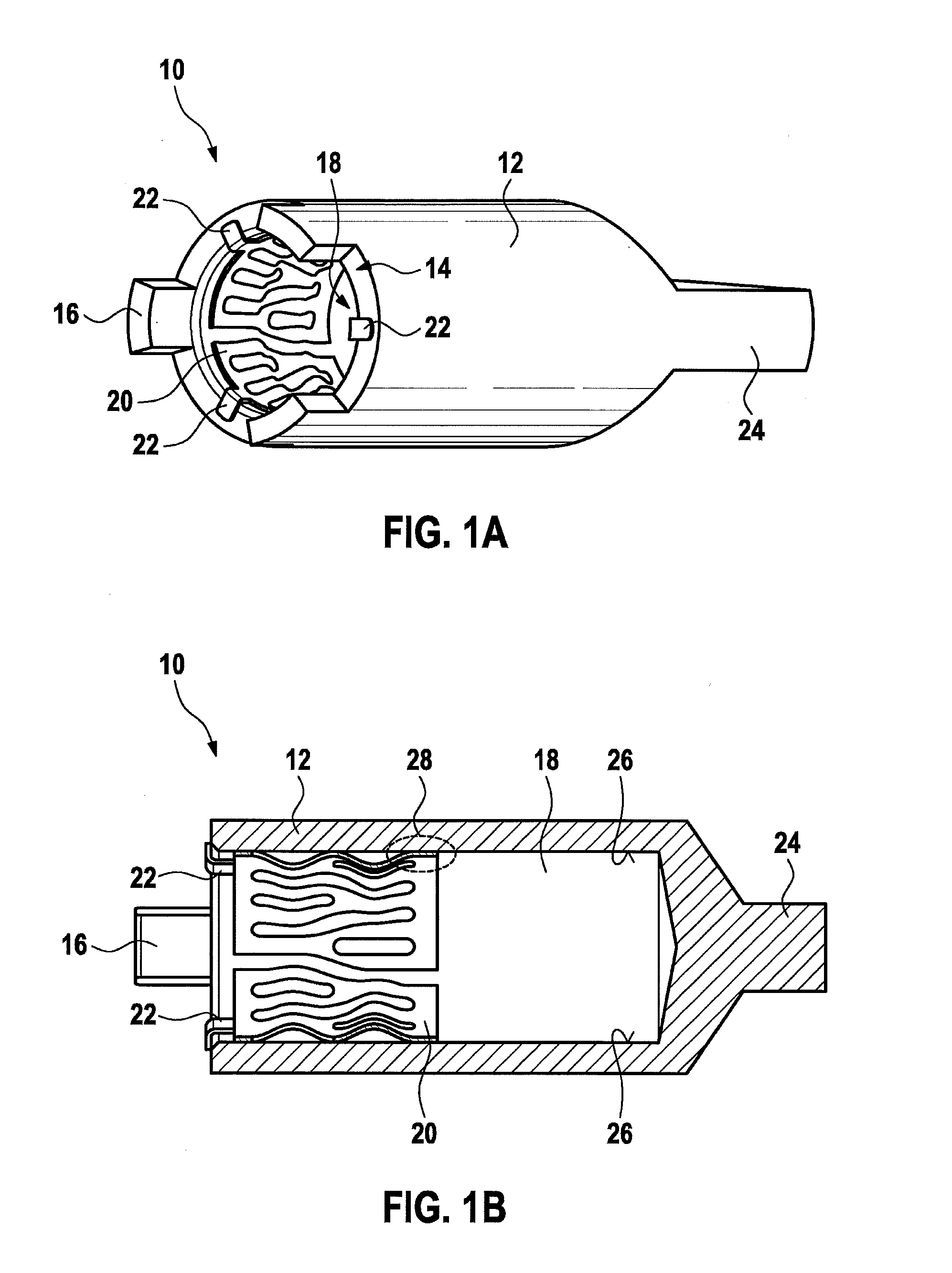
[0032]FIG. 1A shows a simplified configuration of a socket 10 together with a contact sleeve 12. In the example shown here, contact sleeve 12 includes at least one recess 14 and at least one locking pin 16—in the exemplary embodiment illustrated, three recesses 14 and three locking pins 16 each—at the edge of a facing side for inserting a contact pin (not illustrated). Recess 14 and locking pin 16 may be understood as additional features of socket 10 which may be used for mechanical stabilization. A contacting system 20 is situated in an inner area 18 of contact sleeve 12. On a side facing the end-face side of contact sleeve 12, contacting system 20 has multiple protrusions 22 in the radial direction which rest against the end-face side of contact sleeve 12 in such a way that contacting system 20 is prevented from unintentionally moving too far into inner area 18 of contact sleeve 12 when a contact pin (not shown) is inserted. An axial support of protrusions 22 is also conceivable. ...


PUM


Abstract

A socket for a high-current plug-in connection is provided, which includes a contact sleeve and a hollow cylindrical contacting system. The contacting system includes a plurality of elongated contact lamellae, is situated in an inner area of the contact sleeve, and is supported with at least a portion of its outer wall on the inner wall. The contact lamellae extend between a first collar and a second collar of the contacting system. The socket includes a contact lamella, in an area between the first collar and second collar, having an arm, via which the contact lamella is additionally connected to a collar of the contacting system in a supporting manner.

Description

BACKGROUND INFORMATION[0001]Today, high electrical current intensities are transferred in many fields of technology. In recent years, increasingly higher currents are being transferred, also in modern vehicles in growing numbers, in particular in the area of electromobility or hybrid vehicles.[0002]In particular when connecting elements and contact elements are used, various requirements for secure contacting, and at the same time low electrical resistance and high service life, are often imposed. In addition, for use in motor vehicles, additional specific requirements may apply for a plug-in connection, for example due to vibrations which occur or use-related temperature fluctuations.[0003]German Patent Application No. DE 10 2004 029 834 A1 describes an electrical contact element in the form of a coil spring having multiple windings. The windings have the shape of a polygon, which allows transfer of a high current. A low insertion force and a high tolerance compensation are thus pr...

Claims


Application Information

Patent Timeline
Patent Type & Authority Applications(United States)
IPC IPC(8): H01R4/48
CPCH01R4/48H01R13/187
Inventor SAUR, MARTINHU, ZHENYU
Owner ROBERT BOSCH GMBH
Why Eureka
Try Eureka