Device for continuous filtration of material blends

a technology of material blends and filters, applied in the direction of filtration separation, separation processes, applications, etc., can solve the problems of residues being transported to the two outlet openings for a relatively long time, clogging of filter openings, and affecting the filtration body, so as to improve the stability of the device, reduce the abrasive wear of the filter, and reduce the effect of wear and tear

Inactive Publication Date: 2006-10-24
ETTLINGER KUNSTSTOFFMANSCHINEN GMBH
View PDF18 Cites 5 Cited by
  • Summary
  • Abstract
  • Description
  • Claims
  • Application Information

AI Technical Summary

Benefits of technology

[0010]An important advantage of the device according to the present invention is that the filter residues are lifted from the surface of the filter without further touching the filter. During filter cleaning, the residues are not pushed along the surface of the filter, thus reducing the wear and tear and making it possible to improve the stability of the device. Because of the lower abrasive wear of the filter, it is also possible to use less expensive filters of a less complex construction.
[0011]A filter that can be easily manufactured comprises a filter tube on which a plurality of thru openings are disposed and which is supported by a supporting body. The filter tube is preferably made of a wear-resistant material to which optionally an additional coating can be applied. The thru openings preferably have a cross section that widens in the direction of flow and can have the form of conical borings produced, e.g., by electron ray or laser processing. The supporting body is preferably a hollow cylinder which, on the bearing surface for the supporting tube [sic], has a number of circumferential collecting grooves with narrow riblike contact members in between. Thus, an inexpensive filter with a large open filter surface is made possible. The filter is extremely wear-resistant and, if necessary, can be easily replaced.
[0012]The material removed by the scraper is preferably transported off by means of a conveying device. The filter and the conveying device can be driven separately, thus making it possible to separately control the cleaning rate and the rate at which the foreign substances are discharged. This type of control makes it possible to obtain a very high concentration of foreign substances and thus a high yield of the primary material. In one useful embodiment, the conveying device is a motor-driven rotary-drive conveying screw. The rotational speeds of the filter and of the conveying screw can be controlled separately of each other, which makes it possible to obtain a very high concentration of impurities and simultaneously have an optimum active filter surface. Depending on the type of plastic involved, the filter and the conveying screw can have identical or opposite directions of rotation.

Problems solved by technology

In this embodiment, the transporting path for discharging the residues, however, extends across the entire inside surface of the filter, which can quickly put considerable strain on the filtration body, especially if the residues are hard and abrasive.
Furthermore, because of the axial movement of the residues along the filter, the filter openings can easily become clogged.
In addition, the filtration body of this known separating unit is supported on the housing by means of a constructively complex supporting unit.
However, in this case, the residues being transported to the two outlet openings are again moved for a relatively long time along the inside wall of the filter.

Method used


Image

  • Device for continuous filtration of material blends
  • Device for continuous filtration of material blends
  • Device for continuous filtration of material blends

Examples


Embodiment Construction

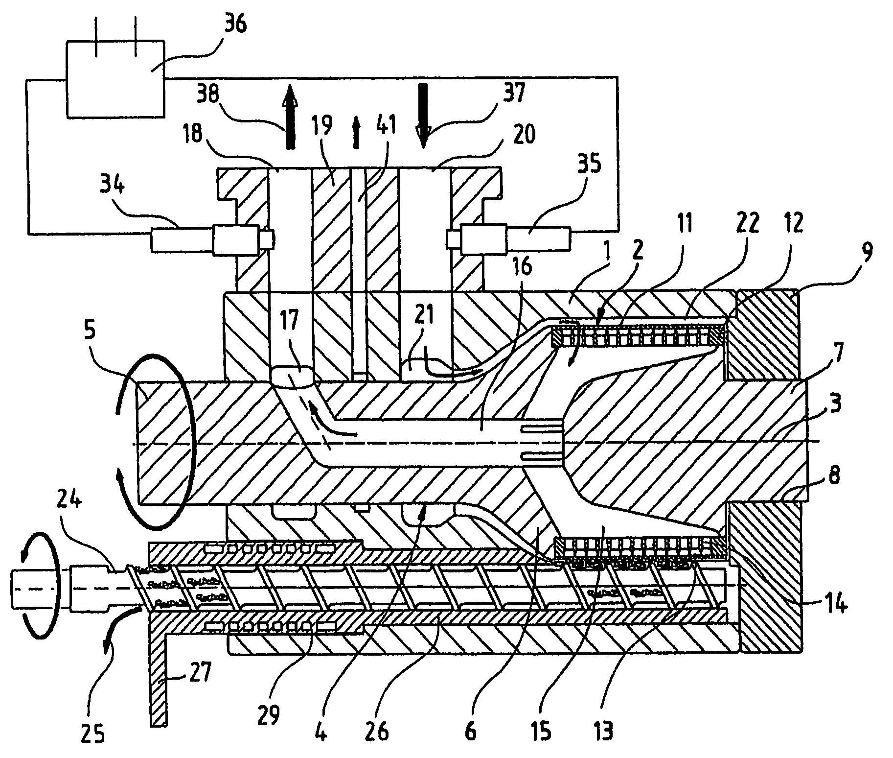
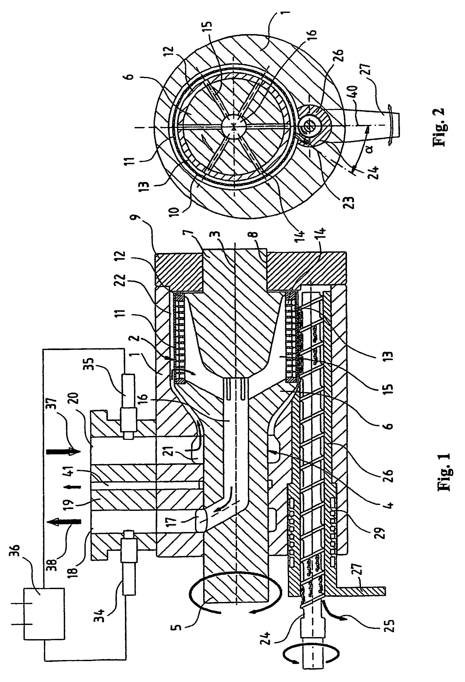
[0020]The separating device for filtering contaminated plastic melts diagrammatically shown in FIG. 1 comprises a housing 1 in which a melt filtration unit 2 in the shape of a hollow cylinder is disposed so as to be able to pivot about the axis of rotation 3. The melt filtration unit 2 is mounted on a motor-driven rotary-drive carrier shaft 4. This carrier shaft comprises a relatively slim drive element 5 that is disposed inside housing 1, a wider bearing element 6 for melt filtration unit 2, and a slimmer journal 7 which is pivoted in a suitable boring 8 of a bearing cap 9 that is attached to housing 1.

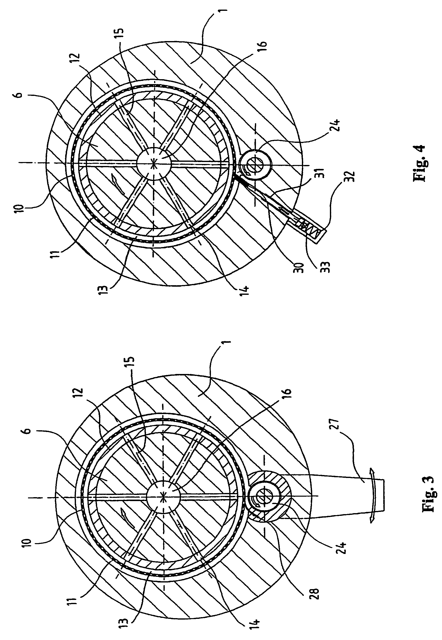
[0021]The melt filtration unit 2, which is shown enlarged in FIG. 5, comprises a filter tube 11 which has a plurality of radial thru openings 10 and a hollow cylindrical supporting body 12 which is form-fittingly connected to the carrier shaft 4 and onto which filter tube 11 is shrink-fitted. The strainer-like filter tube 11 can be fashioned, e.g., from sheet steel with thru openings...


PUM

PropertyMeasurementUnit
angle of pitchaaaaaaaaaa
oblique angleaaaaaaaaaa
angle of pitchaaaaaaaaaa

Abstract

A device for the continuous filtration of material blends, in particular for separating impurities from plastic melts. A housing has a hollow cylindrical filter disposed inside. An inside chamber is disposed inside the filter. An annular chamber is defined by the outer surface of the filter and an inside wall of the housing. A cleaning device removes the impurities retained on the filter by a motor driving about an axis coupled to pivot the filter inside the housing. The cleaning device has at least one wiper for removing in the radial direction impurities retained on the filter. A conveying device transports off the impurities removed from the filter by the wiper. The motor-driven filter and the conveying device are driven separately of each other.

Description

RELATED APPLICATION[0001]This application is a continuation of International application serial no. PCT / EP2003 / 005015 filed May 14, 2003, the contents of which are here incorporated by reference in their entirety. The benefit of 35 USC § 120 is here claimed.BACKGROUND OF THE INVENTION[0002]1. Field of the Invention[0003]The subject matter of the present invention relates to a device for the continuous filtration of material blends, in particular for separating impurities from plastic melts.[0004]2. Prior Art[0005]Used plastics and plastic waste normally contain high quantities of foreign substances, e.g., metal parts, paper residues, glass, secondary plastics, etc. As a rule, these foreign substances or impurities must be removed prior to the recycling of the plastics. In many cases, this is accomplished by first plastifying the used plastic materials by heating them and by subsequently filtering the plastic melt. For this purpose, so-called melt filtration units are used, by means ...

Claims


Application Information

Patent Timeline
Patent Type & Authority Patents(United States)
IPC IPC(8): B29C47/68B01D33/06B01D33/46B29B13/10B01D33/00B01D33/073B01D33/11B29C48/03B29C48/694B65B11/52B65B25/06
CPCB01D33/0009B01D33/073B01D33/11B29C47/0888B29C47/684B29C47/687B01D33/466B01D33/465B29C47/0009B29C48/03B29C48/2735B29C48/6916B29C48/694B01D33/46B01D33/06B29B13/10
Inventor ETTLINGER, RODERICH
Owner ETTLINGER KUNSTSTOFFMANSCHINEN GMBH
Why Eureka
Try Eureka