

Iv set having an air stop membrane
a technology of air stop and iv set, which is applied in the field of iv set having an air stop membrane, can solve the problems of affecting the operation of the iv set, and affecting the patient's breathing, and the process of complete removal of air bubbles can be time-consuming and laborious
- Summary
- Abstract
- Description
- Claims
- Application Information
AI Technical Summary
Benefits of technology
Problems solved by technology
Method used
Image

Examples
first embodiment
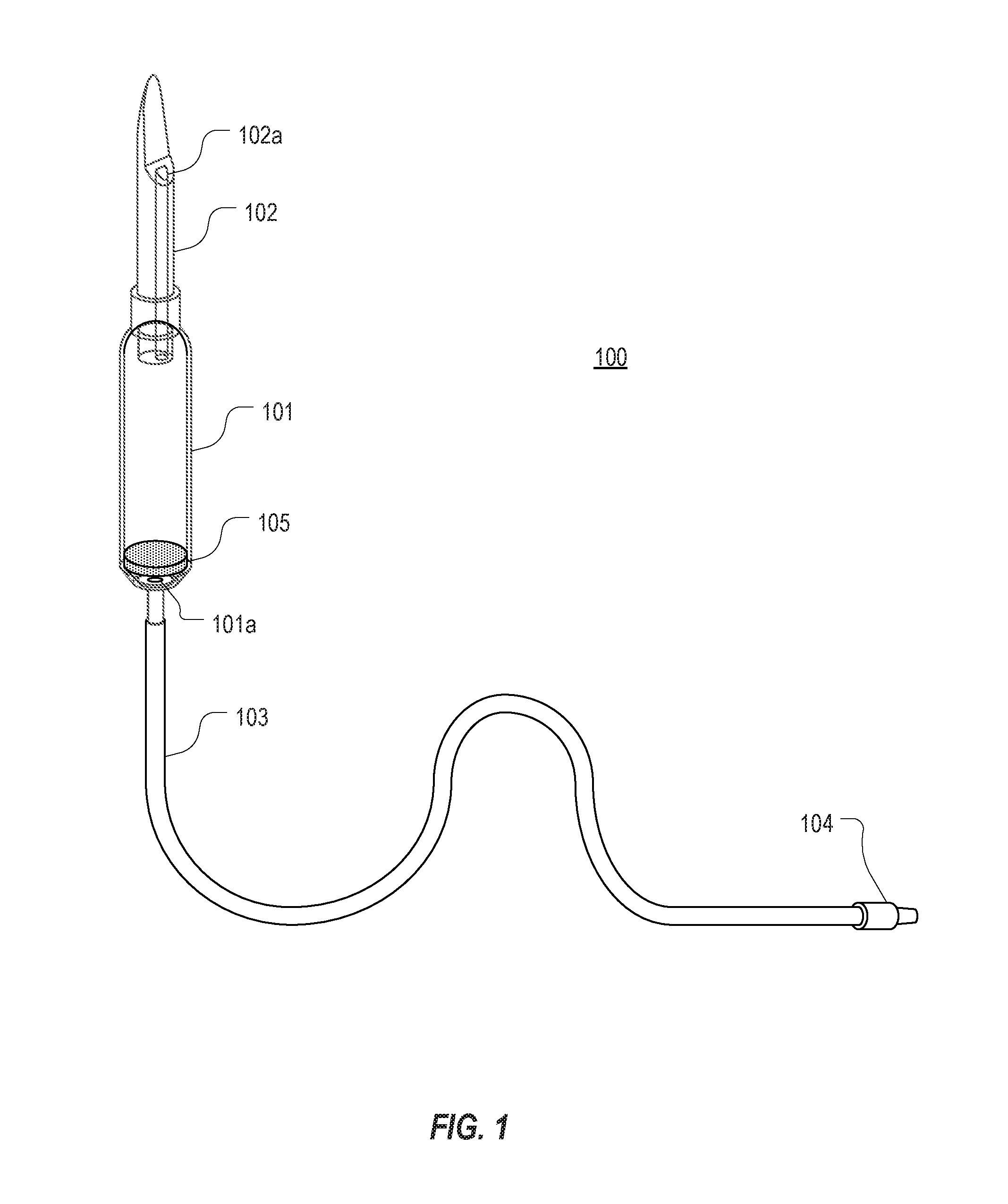
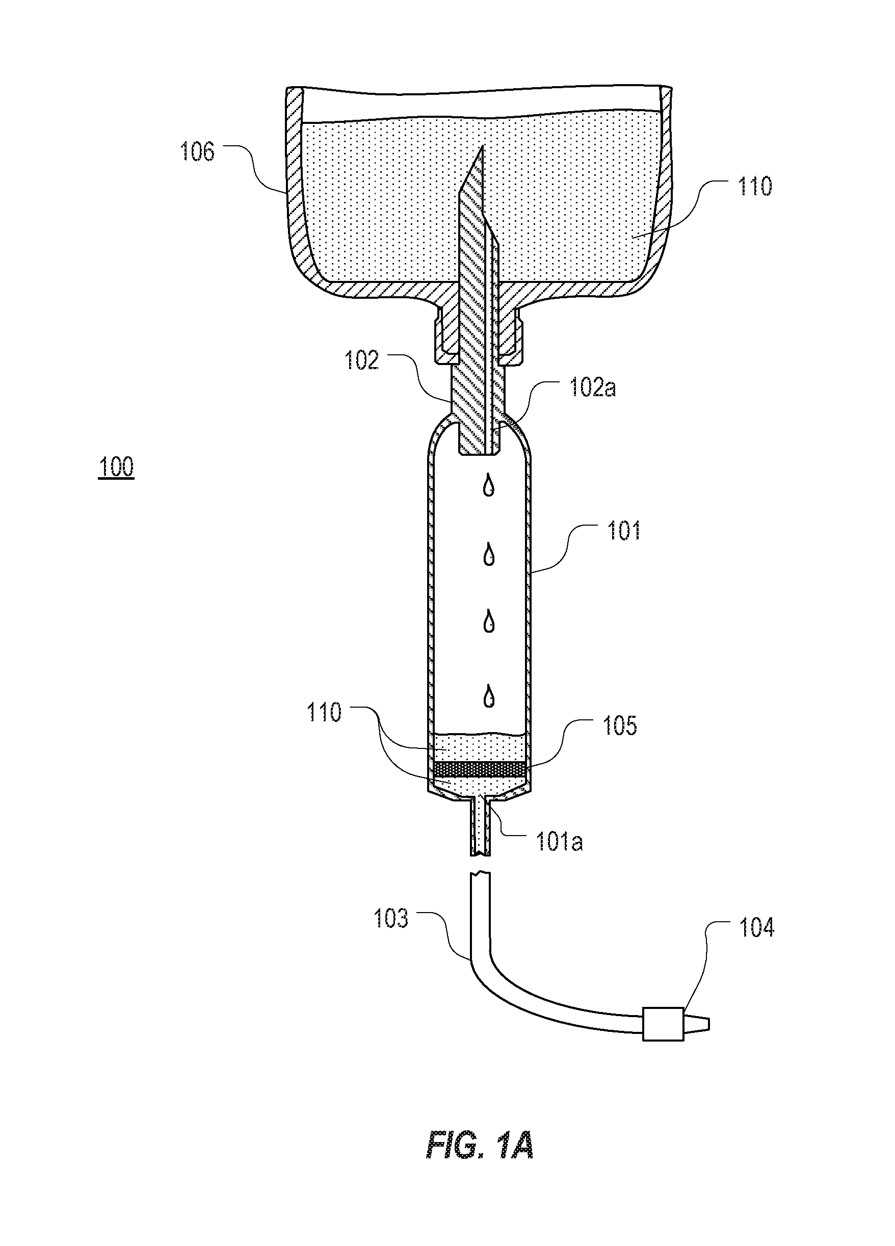
[0044]Referring now to FIG. 1, an IV set 100 that includes an air stop membrane is shown. IV set 100 includes a drip chamber 101, a spike 102 for coupling IV set 100 to a fluid bag or other fluid reservoir, tubing 103 for carrying fluid from drip chamber 101 to the patient, and a coupler 104 for coupling tubing 103 to an intravenous device such as a catheter. Typically, spike 102 would be coupled to a fluid bag that is elevated above the patient to allow gravity to pull the fluid through the IV set. However, spike 102 may also be coupled to a fluid bag that employs a pump to distribute the fluid. Spike 102 forms a fluid pathway 102a to allow fluid to flow from a fluid bag into drip chamber 101. Drip chamber 101 includes a distal opening 101a through which fluid flows from drip chamber 101 and into tubing 103. Coupler 104 can typically be a male luer connector although any suitable connector could be employed.
[0045]Although not shown, IV set 100 (and other IV sets described in this s...
second embodiment
[0052]Referring now to FIG. 2, an IV set 200 that includes an air stop membrane is shown. IV set 200 is similar to IV set 100 except that IV set 200 includes an air stop membrane 205 that is positioned in a chamber 202a within spike 202. For purposes of this specification, a spike can be construed as including an air stop membrane if the air stop membrane is positioned in a chamber that is above the drip chamber.
[0053]As with IV set 100, IV set 200 includes a drip chamber 202 coupled to spike 202, tubing 203 coupled to drip chamber 202, and a coupler 204 configured to connect tubing 203 to a vascular access device. Spike 202 includes a distal opening 202b through which fluid drips into drip chamber 201. Similarly, drip chamber 201 includes a distal opening 201a through which fluid passes into tubing 203.
[0054]FIGS. 2A and 2B provide cross-sectional views of IV set 200 while spike 202 is coupled to a fluid bag 206. In FIG. 2A, fluid bag 206 still contains fluid 210 and therefore flui...
third embodiment
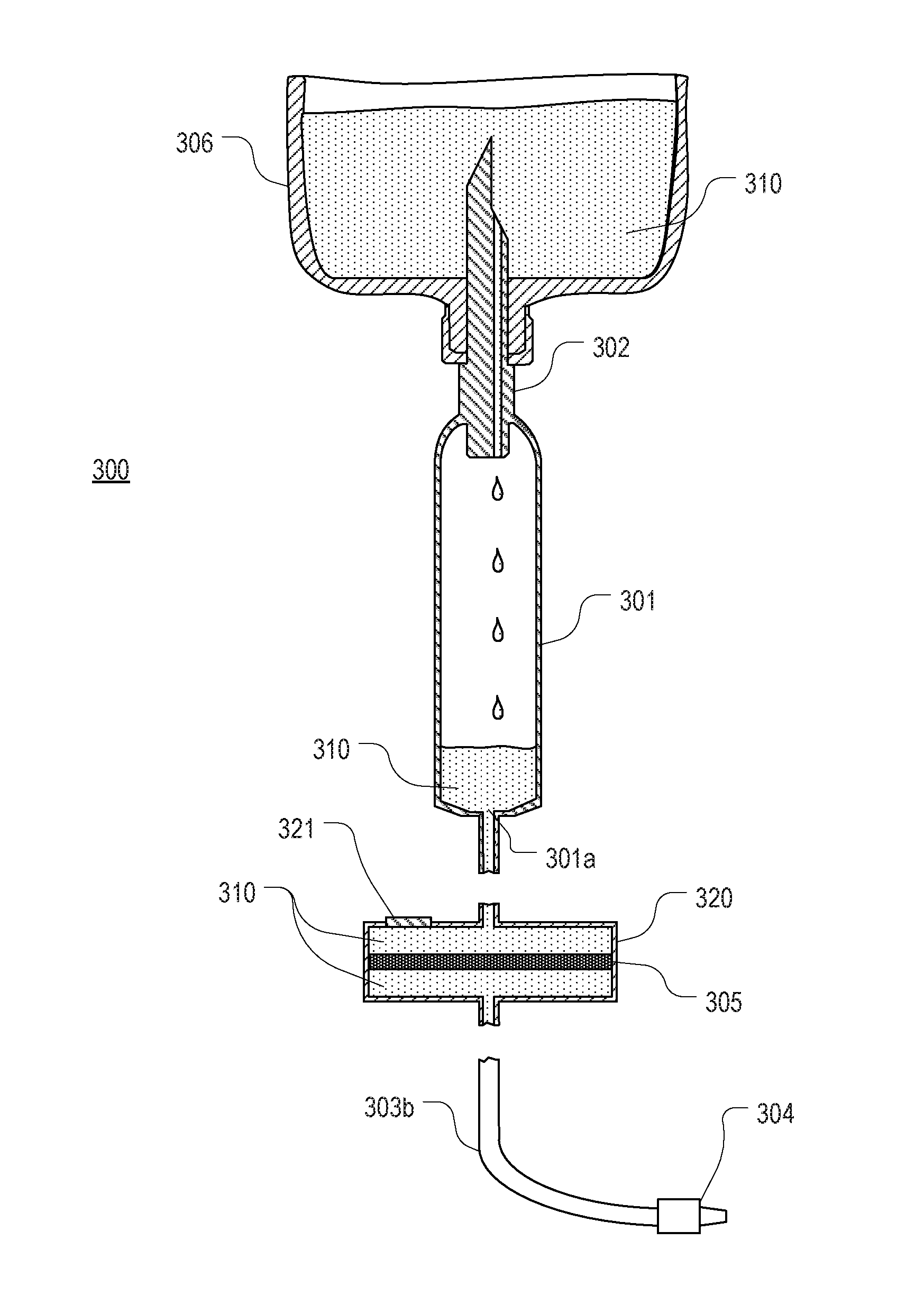
[0060]Referring now to FIG. 3, an IV set 300 that includes an air stop membrane is shown. IV set 300 includes a drip chamber 301 and a spike 302 that includes a fluid pathway 302a through which fluid from a fluid bag flows into drip chamber 301. IV set 300 also includes a membrane housing 320 within which an air stop membrane 305 is positioned. Tubing 303a couples drip chamber 301 to membrane housing 320 while tubing 303b extends from a distal opening of membrane housing 320 and includes a coupler 304 for coupling tubing 303b to a vascular access device. Membrane housing 320 also includes an air vent 321 through which air may be vented during priming of IV set 300. Air vent 321 can include a hydrophobic membrane or other filter that allows air but not fluid to pass. Air vent 321 can preferably be configured to allow IV set 300 to be primed in less than 15 seconds. In some embodiments, membrane housing 310 can be configured to couple directly to drip chamber 301 such that tubing 303a...
PUM
 Abstract
Description
Claims
Application Information