Methods and systems for wind plant power optimization

a wind power plant and optimization technology, applied in active/predictive/anticipative control, mechanical equipment, machines/engines, etc., can solve the problems of inability to respond quickly enough to make a sustainable improvement, the complexity of wind and turbine wake interaction dynamically occurring in the actual atmospheric environment of the wind power plant, and the negative impact of performan

Inactive Publication Date: 2016-07-28
ALLIANCE FOR SUSTAINABLE ENERGY
View PDF4 Cites 38 Cited by
  • Summary
  • Abstract
  • Description
  • Claims
  • Application Information

AI Technical Summary

Benefits of technology

[0005]In one example, a method includes receiving, by a computing system, at least one sensor measurement, the at least one sensor measurement including at least one of a wind speed measurement, or a wind direction measurement. The method also includes determining, by the computing system, using a stochastic filter, and based on the at least one sensor measurement, at least one predicted attribute of a wake generated by a wind turbine. The wind turbine may be one of a plurality of wind turbines of a wind plant. The method further includes modifying, by the computing system and based on the at least one predicted attribute of the wake, at least one wind turbine control variable for at least one wind turbine of the plurality of wind turbines, and outputting, by the computing system, the at least one wind turbine control variable.
[0006]In another example, a system includes at least one processor and at least one module operable by the at least one processor to receive at least one sensor measurement. The at least one sensor measurement may include at least one of a wind speed measurement, or a wind direction measurement. The at least one module is further operable by the at least one processor to determine, using a stochastic filter, and based on the at least one sensor measurement, at least one predicted attribute of a wake generated by a wind turbine, the wi...

Problems solved by technology

In general, related art methods look to improve performance by accounting for the way turbines interact in a plant through their wakes, which can negatively impact performance.
However, one obstacle to the introduction of optimization methods to actual wind plants in the field has been the complexity of wind and turbine wake interactions dynamically occurring in the...

Method used


Image

  • Methods and systems for wind plant power optimization
  • Methods and systems for wind plant power optimization
  • Methods and systems for wind plant power optimization

Examples


example a

[0057]An example of how separate subweight computations may be performed follows below. Note that in this example, when a weighting function applies to a single wake trajectory, the total subweight value may be the sum of a computed penalty (described below) for each trajectory in the particle.

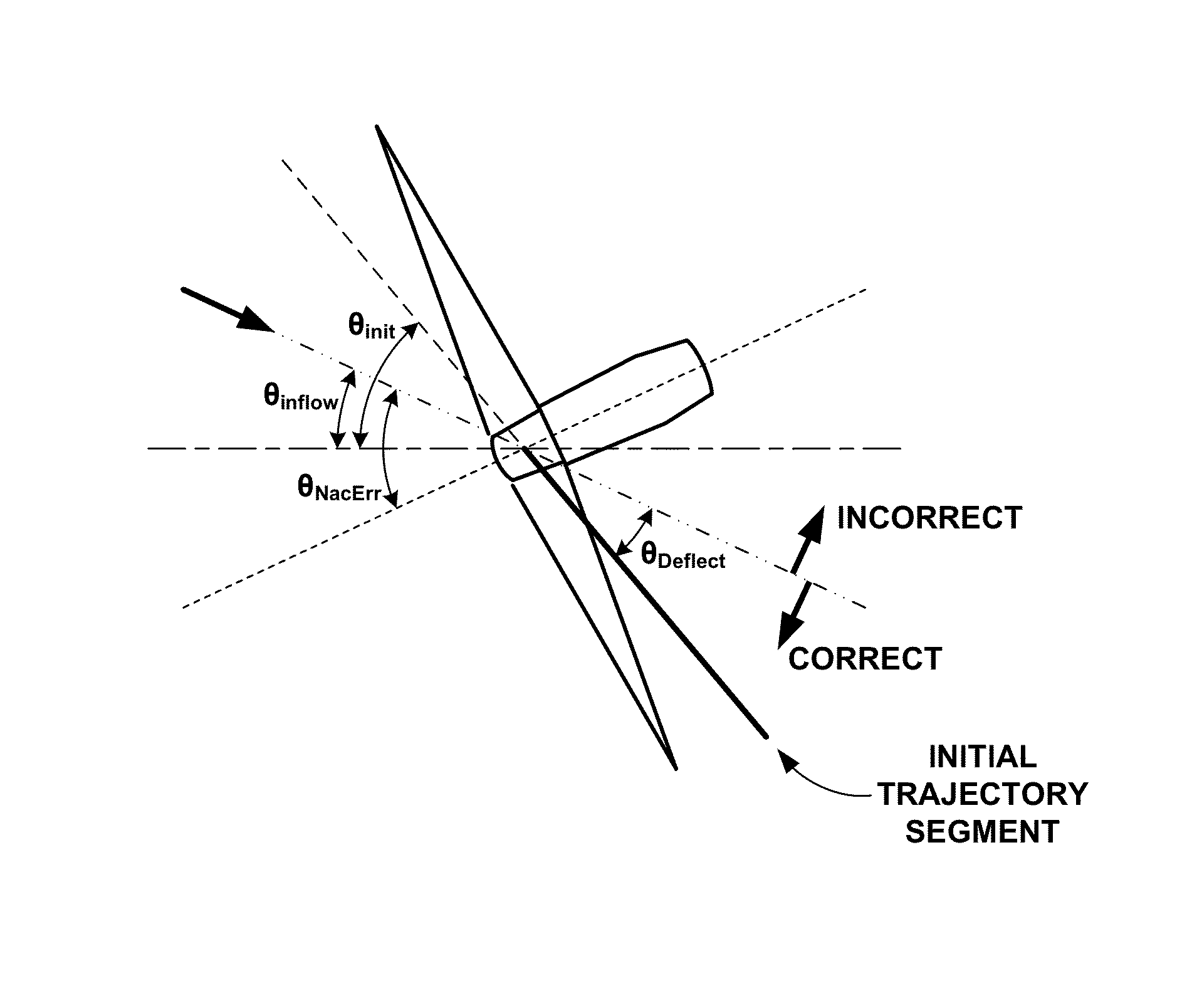
[0058]Deflection: In this example method of a subweight computation, a first subweight is meant to penalize an initial wake angle (θinit), which conflicts with assumptions about the relationship between yaw misalignment and the deflection of the wake with respect to the inflow direction. An assumption is made that the direction of the deflection is consistent across turbines, however, as illustrated in FIG. 5.

[0059]Referring to FIG. 5, θinflow is defined as the angle of the inflow angle with respect to a reference axis shown as a short then long dashed horizontal line in FIG. 5, while θNacErr is defined as the angle between the yaw alignment of the turbine with respect to the inflow direction....

example b

[0070]Based on the features described above, a particle filter method was tested to determine the method's capabilities at predicting wind plant turbine wake locations. This testing was enabled by the use of a high fidelity wind plant simulation tool developed at the National Renewable Energy Laboratory (NREL): the Simulator for Onshore / Offshore Wind Farm Applications (SOWFA). Within SOWFA, several wind plant scenarios were carried out, utilizing virtual turbine measurements (such as nacelle wind speed, wind direction, and blade bending), and these computational fluid dynamic (CFD) outputs were used to run the particle filtering method described above. In addition, horizontal slices from the flow-field at hub height were extracted, in which turbine wakes are clearly visible and provide a way to evaluate the performance of the particle filter technique.

[0071]Regarding the simulation tool utilized for the following experiments, SOWFA is a CFD tool used to model wind turbines in a flow...

example 1

[0100]A method comprising: receiving, by a computing system, at least one sensor measurement, wherein the at least one sensor measurement comprises at least one of a wind speed measurement, or a wind direction measurement; determining, by the computing system, using a stochastic filter, and based on the at least one sensor measurement, at least one predicted attribute of a wake generated by a wind turbine, wherein the wind turbine is one of a plurality of wind turbines of a wind plant; modifying, by the computing system and based on the at least one predicted attribute of the wake, at least one wind turbine control variable for at least one wind turbine of the plurality of wind turbines; and outputting, by the computing system, the at least one wind turbine control variable.


PUM


Abstract

A system includes at least one processor and at least one module operable by the at least one processor to receive at least one sensor measurement. The at least one sensor measurement may include at least one of a wind speed measurement, or a wind direction measurement. The at least one module may be further operable to determine, using a stochastic filter, and based on the at least one sensor measurement, at least one predicted attribute of a wake generated by a wind turbine, the wind turbine being one of a plurality of wind turbines of a wind plant. The at least one module may be further operable to modify, based on the at least one predicted attribute of the wake, at least one wind turbine control variable for at least one wind turbine of the plurality of wind turbines and output the at least one wind turbine control variable

Description

[0001]This application claims the benefit of U.S. Provisional Application No. 62 / 109,009, filed Jan. 28, 2015 and titled “METHODS AND SYSTEM FOR CONTROLLING THE POWER OUTPUT FROM A WIND PLANT,” the entire content of which is incorporated herein by reference.CONTRACTUAL ORIGIN[0002]The United States Government has rights in this invention under Contract No. DE-AC36-08GO28308 between the United States Department of Energy and Alliance for Sustainable Energy, LLC, the Manager and Operator of the National Renewable Energy Laboratory.BACKGROUND OF DISCLOSURE[0003]There is a growing interest in the design of wind plant control systems to coordinate the controls of individual turbines to achieve improvements in the overall wind plant performance, such as total power production. In some related art methods, individual turbine controls are adjusted to improve the total output of the plant above what would be achieved if each turbine pursued its individual optimal output. In general, related ...

Claims


Application Information

Patent Timeline
IPC IPC(8): F03D7/04
CPCF03D7/046F03D7/048F05B2260/8211F05B2270/32F05B2270/321F05B2270/404F05B2270/204Y02E10/72
Inventor FLEMING, PAULGEBRAAD, PIETER M.O.
Owner ALLIANCE FOR SUSTAINABLE ENERGY
Why Eureka
Try Eureka