
Carbon-dioxide recovery apparatus, and carbon-dioxide recovery method

a carbon dioxide and apparatus technology, applied in the field of carbon dioxide recovery apparatus and carbon dioxide recovery method, can solve the problems of increasing the operation cost of gas-liquid separation of recovered carbon dioxide, and affecting the recovery effect of carbon dioxide, etc., to achieve the effect of increasing energy efficiency and shortening the tim

Inactive Publication Date: 2016-08-04
HITACHI CHEM CO LTD
View PDF6 Cites 4 Cited by
  • Summary
  • Abstract
  • Description
  • Claims
  • Application Information

AI Technical Summary

Benefits of technology

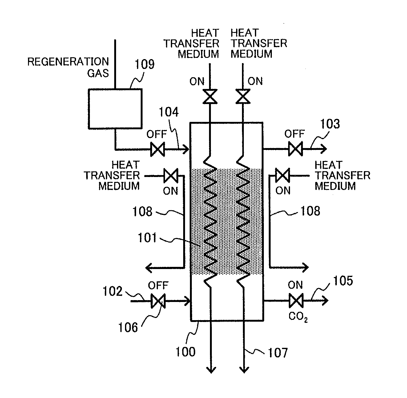
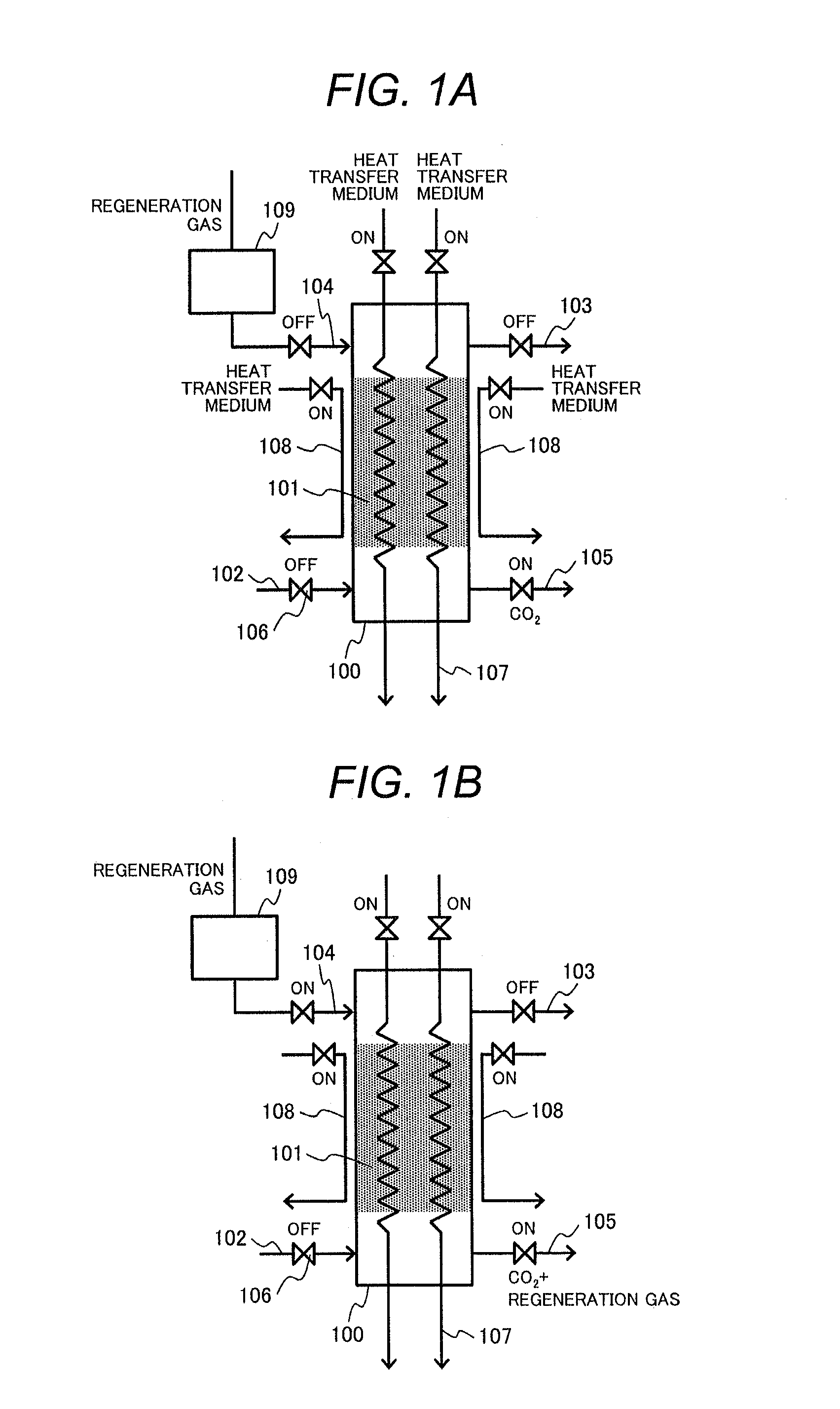
The present invention reduces the amount of gas needed for regenerating a material used to capture carbon dioxide, increases energy efficiency, and reduces the time required for regeneration.

Problems solved by technology

Typically disadvantageously, however, steam condensation occurs at a carbon dioxide capturing material (adsorbent) surface due to steam flow when the carbon dioxide capturing material has a temperature lower than the steam temperature.
Disadvantageously, however, the steam is continuously supplied during the regeneration of the carbon dioxide absorbent, and this leads to great loss of condensation heat and increased operation cost upon gas-liquid separation of the recovered carbon dioxide from the steam.

Method used


Image

  • Carbon-dioxide recovery apparatus, and carbon-dioxide recovery method
  • Carbon-dioxide recovery apparatus, and carbon-dioxide recovery method
  • Carbon-dioxide recovery apparatus, and carbon-dioxide recovery method

Examples


example 1

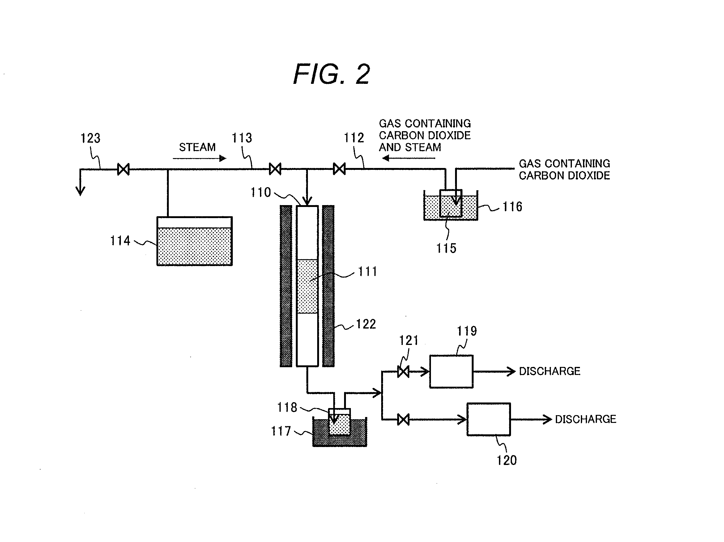
[0060]A test including a sorbing step and a desorbing step was performed as Example 1 by a procedure similar to Comparative Example 1. However, the output of the steam generator was changed, and the flow rate of the generated steam was measured via the steam flow measurement channel and was found to be 2781 cc / min, corresponding to 0.5 m / sec in terms of the linear velocity in the tubular reactor. An integrated flow rate was calculated based on data from the flow rate measuring and recording means (flowmeter) 120, based on which a change with time of the integrated carbon dioxide desorption during the steam supply was determined.

example 2

[0061]A test including a sorbing step and a desorbing step was performed as Example 2 by a procedure similar to Comparative Example 1. However, the output of the steam generator was changed, and the flow rate of the generated steam was measured via the steam flow measurement channel and was found to be 7021 cc / min, corresponding to 1.3 m / sec in terms of the linear velocity in the tubular reactor. An integrated flow rate was calculated based on data from the flow rate measuring and recording means (flowmeter) 120, based on which a change with time of the integrated carbon dioxide desorption during the steam supply was determined.

example 3

[0062]A test including a sorbing step and a desorbing step was performed as Example 3 by a procedure similar to Comparative Example 1. However, the output of the steam generator was changed, and the flow rate of the generated steam was measured via the steam flow measurement channel and was found to be 10691 cc / min, which corresponds to 2.0 m / sec in terms of the linear velocity in the tubular reactor. An integrated flow rate was calculated based on data from the flow rate measuring and recording means (flowmeter) 120, based on which a change with time of the integrated carbon dioxide desorption during the steam supply was determined.

[0063]FIG. 3 presents the integrated desorbed amounts of CO2 upon lapse of 0.5 min, 1 min, 1.5 min, 2 min, and 2.5 min. The abscissa indicates the linear velocity of the steam in Comparative Example 1 and Examples 1 to 3.

[0064]FIG. 4 presents the time taken to desorb the whole quantity of CO2 after the steam supply start.

[0065]In FIGS. 3 and 4, Comparati...


PUM

PropertyMeasurementUnit
linear velocityaaaaaaaaaa
boiling pointaaaaaaaaaa
pressureaaaaaaaaaa

Abstract

In regenerating carbon dioxide capturing material, the amount of regeneration gas supplied to a carbon dioxide recovery column is reduced for higher energy efficiency and shortened regeneration time. A carbon dioxide recovery apparatus includes a carbon dioxide sorbing column, a heating unit, and first, second, and third channels. The carbon dioxide sorbing column contains a carbon dioxide capturing material. The heating unit heats the carbon dioxide capturing material. A carbon-dioxide-containing gas is introduced via the first channel into the carbon dioxide sorbing column. The regeneration gas is introduced via the second channel into the carbon dioxide sorbing column. A gaseous mixture containing a gas desorbed from the carbon dioxide capturing material is recovered via the third channel. The heating unit preheats the carbon dioxide capturing material, and then the regeneration gas is introduced into the carbon dioxide sorbing column to recover carbon dioxide from the carbon dioxide capturing material.

Description

TECHNICAL FIELD[0001]The present invention relates to an apparatus and a method for recovering carbon dioxide using a carbon dioxide capturing material.BACKGROUND ART[0002]For reducing a global warming, it is demanded to reduce a carbon dioxide emission, where carbon dioxide serves as a greenhouse gas and has a great impact on the global warming. Specifically, examples of the carbon dioxide emission control include techniques of separation and recovery typically using an absorbent (absorbing liquid) or an adsorbent.[0003]In a known technique for adsorbing and separating a gas, generally, in order to adsorb and separate a specific component in the gas, the specific component is first adsorbed by an adsorbent contained in an adsorption column. The adsorption column housing the adsorbent adsorbing a predetermined amount of the specific component is then heated, and a gas is supplied thereto to desorb the specific component from the adsorbent and to regenerate the adsorbent.[0004]As the...

Claims


Application Information

Patent Timeline
Patent Type & Authority Applications(United States)
IPC IPC(8): B01D53/04C01B32/50
CPCB01D53/0438B01D2259/40088B01D2253/108B01D2253/204B01D2257/504Y02P20/152Y02P20/57B01J20/06B01J20/34C01B31/20Y02C10/08Y02C10/04B01D2253/1124B01D2259/40086B01D2253/104B01D53/0423B01D53/0462B01D2253/102B01D2253/106B01D2253/1122B01D2253/3425B01D2259/40009B01D2259/4009C01B32/50B01J20/041B01J20/043B01J20/08B01J20/226B01D53/02B01J20/3433B01J20/3458B01D2253/25B01J20/103Y02P20/50Y02C20/40Y02P20/151
Inventor YOSHIKAWA, KOUHEIKANEEDA, MASATONAKAMURA, HIDEHIROSHIRASAKA, TOSHIAKIKITAMURA, KENETSUENOMOTO, KAZUHIRO
Owner HITACHI CHEM CO LTD
Learn More