Low-vibration floating metal bearing

a floating metal bearing and low vibration technology, applied in the direction of bearings, shafts and bearings, rotary bearings, etc., can solve the problems of slide bearings still having a major problem of being more prone to noise, ball bearing turbines basically need a larger amount of oil, and the oil is more prone to deterioration, so as to achieve low rotation, high rotational speed, and high centering

Active Publication Date: 2016-08-04
NAKAMURA IND MFG CO LTD
View PDF0 Cites 4 Cited by
  • Summary
  • Abstract
  • Description
  • Claims
  • Application Information

AI Technical Summary

Benefits of technology

[0016]Inner surface machining is applied to the low-vibration floating metal bearing according to the present invention. The machining continuously disposes in an isogonal and isotropic manner with respect to the axial center, a plurality of regions with different fluid lubrication conditions at isogonal positions in an isotropic manner with respect to the axial center. Each of the regions with different fluid lubrication conditions is one region that connects moderately a narrow flow path and a wide flow path by changing the amount of clearance between the surface of the shaft and the inner surface of the bearing hole. Thus, the present invention produces a high centering effect from a low rotational speed range to a high rotational speed range. The present invention also makes less prone to cause improper vibrations or self-excited vibrations. Therefore, the present invention provides an excellent advantage of suppressing occurrence of noise resulting from these vibrations.
[0017]The low-vibration floating metal bearing according to the present invention is a slide bearing that delivers excellent functional performance with friction characteristics or durability on a par with ball bearings. On the other hand, the low-vibration floating metal bearing does not need oil pressure control or management, or special components that would be required for ball bearings and the like.
[0018]Under the centering effect, when the rotation starts, a dynamic pressure acts so as to move constantly toward the axial center. The dynamic pressure has the effect of suppressing swings. As a result, as compared to normal floating bearings formed by conventional circular shapes, the low-vibration floating metal bearing decreases rotational resistance.

Problems solved by technology

However, the ball bearing turbines basically need a larger amount of oil.
Thus, if the amount of oil is not suppressed by providing an orifice to a banjo bolt of an oil line or other parts, several problems occur due to excessive oil.
Thus, the oil is more prone to deteriorate as compared to the case where the oil is exposed to natural intake air.
However, the slide bearings still have a major problem of being more prone to cause noise as compared to the ball bearings.
The issue of eliminating noise and the like from an object sliding at a high speed cannot be solved immediately.
However, these improvements still cannot be said to be sufficient.
In addition, the foregoing conventional techniques have complicate structures and still have cost-related problems.
In addition, the bearing housing accommodating these components may be difficult to be provided in terms of reduction in space and cost.
Further, the foregoing patent and utility model documents do not suggest or describe any configuration for eliminating noise.
Therefore, the foregoing conventional techniques have not solved the issue of meeting the social demand expected for floating metal bearings.
The inventor then has revealed that, even if high-accuracy roundness characteristics or surface roughness characteristics are improved, it is difficult to suppress occurrence of noise, that is, occurrence of vibrations resulting in the noise.

Method used


Image

  • Low-vibration floating metal bearing
  • Low-vibration floating metal bearing
  • Low-vibration floating metal bearing

Examples


Embodiment Construction

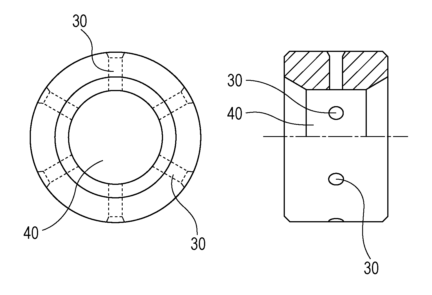
[0028]The largest feature of the present invention resides in applying surface treatment repeatedly to between a narrow flow path and a wide flow path by changing the amount of clearance between the surface of a shaft and an inner surface of a bearing hole 40.

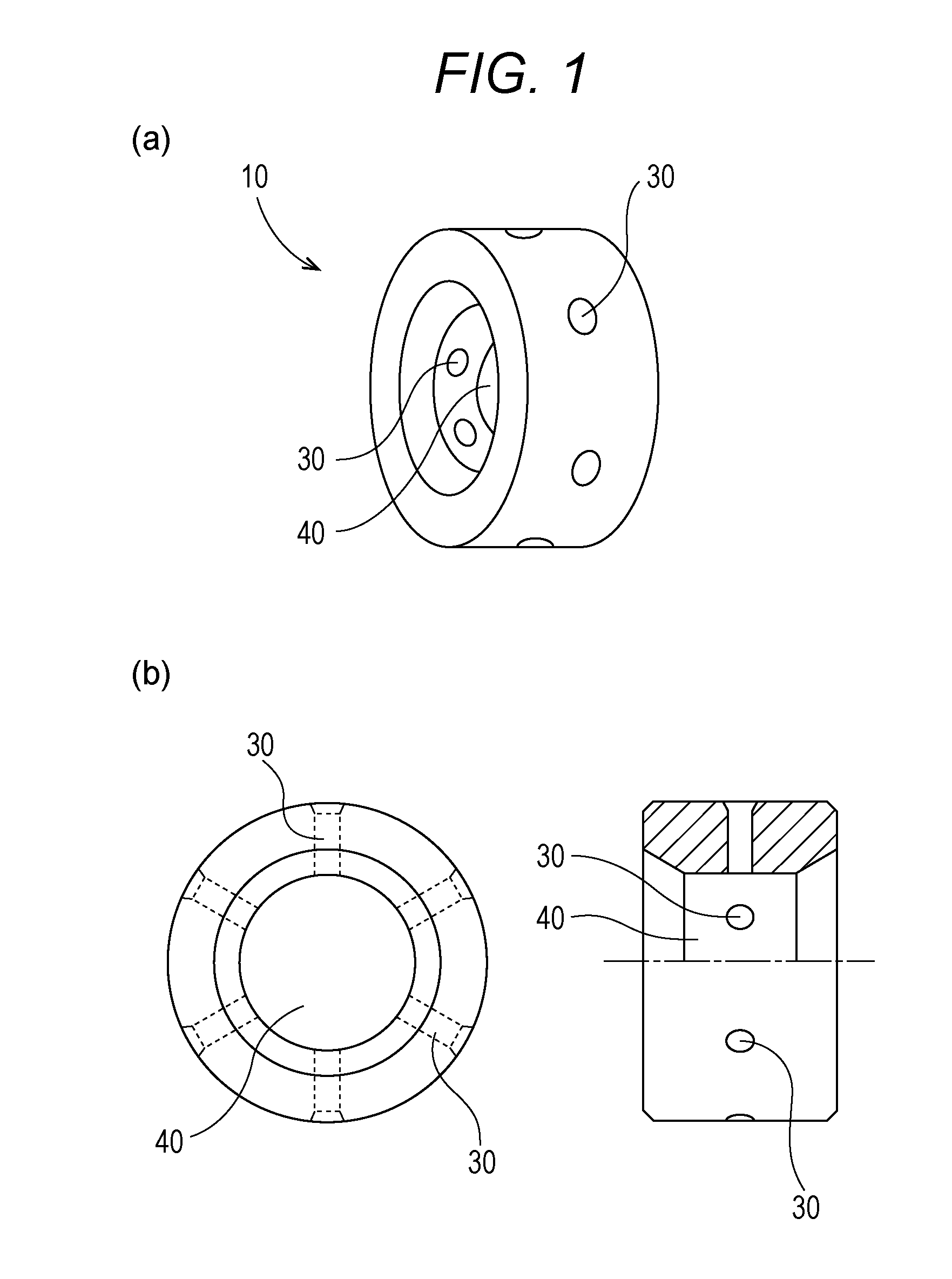
[0029]FIG. 1 is a diagram schematically illustrating a low-vibration floating metal 10 according to the present invention: FIG. 1(a) is a perspective view; and FIG. 1(b) is a plan view and a single cross-section view.

[0030]As illustrated in FIG. 1, the low-vibration floating metal 10 may have an outline similar to that of the normal floating metals. The low-vibration floating metal 10 has a plurality of oil supply holes 30 provided in an isogonal and isotropic manner in the center of the outer peripheral edge. Alternatively, the low-vibration floating metal 10 may have on a periphery thereof an oil supply groove (not illustrated) with the oil holes 30. FIG. 1 illustrates six oil supply holes 30, but the number of the oil supply...


PUM


Abstract

A low-vibration floating metal bearing includes a slide bearing. The slide bearing includes oil supply holes formed at six isogonal positions in an isotropic manner with respect to an axial center, and a substantially circular bearing hole having a surface on which at least six regions with different fluid lubrication conditions are formed by inner machining so as to be continuously disposed at isogonal positions in an isotropic manner with isotropic distance with respect to an axial center. Each of the regions with different fluid lubrication conditions forms a narrow flow path that is substantially convex in cross section and extends in an axial center direction in an oil flow path by changing the amount of clearance between the surface of the substantially circular bearing hole and the surface of a substantially circular axis.

Description

CROSS-REFERENCE TO RELATED APPLICATION[0001]The present application is a 371 of International Application No. PCT / JP2013 / 070764 filed on Jul. 31, 2013, the entire content of which being hereby incorporated herein by reference.TECHNICAL FIELD[0002]The present invention relates to techniques for bearings. More specifically, the present invention relates to a low-vibration floating metal bearing technique. In the present invention, the surface of a bearing hole in a slide bearing is subjected to inner surface machining to provide the surface with a plurality of regions having different fluid lubrication conditions, the regions arranged in an isogonal and isotropic manner with respect to the axial center of the hole. Hence, the present invention makes it possible to exert a high centering effect from a low rotational speed range to a high rotational speed range and suppress occurrence of noise by a vibration suppression effect resulting from the centering effect.BACKGROUND ART[0003]Bear...

Claims


Application Information

Patent Timeline
Patent Type & Authority Applications(United States)
IPC IPC(8): F16C32/06
CPCF16C17/18F16C32/0655F16C33/1045F16C17/028F16C33/14F16C2360/24F16C33/1085F16C32/0651F16C33/1075
Inventor NAKAMURA, SHOTARO
Owner NAKAMURA IND MFG CO LTD
Why Eureka
Try Eureka