Hard-faced friction mating member

a friction mating member and hard-face technology, applied in the field of contact parts, can solve the problems of unstable friction coefficient between the friction member and the friction mating member, noise and vibration generation, and change of friction coefficient, and achieve the effects of small friction coefficient, high speed range, and increased friction coefficien

Inactive Publication Date: 2006-02-28
DAINATSUKUSU
View PDF4 Cites 2 Cited by
  • Summary
  • Abstract
  • Description
  • Claims
  • Application Information

AI Technical Summary

Benefits of technology

[0020]FIG. 7 is a second diagram showing the shudder-suppressing effect of the invention; and
[0021]FIG. 8 is a diagram showing friction coefficients of friction mating members in an example in accordance with the invention, and in comparative example 4 in a low-speed range, and the μ-V characteristics of the friction mating members of the example in accordance with the invention and comparative example 4, for different types of lubricating oils.
[0022]As shown in FIG. 1, the friction mating member 10 is formed by providing a surface of a base member 30 with a hard coating 20. The hard coating 20 has a load point displacement characteristic in which the ratio of elastic deformation to maximum indentation depth (hereinafter referred to as the “elastic range”), in a load range of 1 to 50 mN, is at least 50%. The load point displacement characteristic is measured by a measuring method specified in ISO 14577-1. Since the hard coating 20 has an elastic range of at least 50%, a small friction coefficient can be provided in the low-speed range.
[0023]A hard coating 20 having an elastic range of at least 50% can be formed by depositing amorphous carbon, or a composite material containing amorphous carbon and tungsten carbide, onto the base member 30 by physical vapor deposition or chemical vapor deposition. Semispherical protrusions 40, composed of the same material as that forming the hard coating 20, are formed on the outer surface of the hard coating 20. The semispherical protrusions 40 can also be formed on the surface of the hard coating 20 by depositing amorphous carbon, or a composite material containing amorphous carbon and tungsten carbide, onto the base member 30 by a physical vapor deposition or chemical vapor deposition. The semispherical protrusions 40 increase the friction coefficient in the high speed range by slightly grinding, and smoothing the surface of, the mating friction member.
[0024]The diameters of the semispherical protrusions are in the range of 1 to 5 μm. The friction member will be abraded excessively if the semi-spherical protrusions 40 have diameters greater than 5 μm.
[0025]Preferably, the ratio of an area occupied by all the semispherical protrusions 40 to the area of the surface of the hard coating 20 is at least 3%. If this ratio is less than 3%, the load on the semispherical protrusions 40 becomes excessive, and the semispherical protrusions 40 will wear out rapidly and become unable to exert a slight grinding action on the friction member, and the surface of the friction member will not be made smooth.

Problems solved by technology

In the initial stage of use, before the friction members and the friction mating members have adapted to each other, the friction coefficient between the friction members and the friction mating members is unstable, and the friction device exhibits a phenomenon known as “shudder,” sometimes referred to as “judder,” characterized by the generation of noise and vibration as the friction members and the friction mating members become engaged with one another.
However, the friction coefficient in the low-speed range is highly dependent on the effect of the friction modifier (FM) contained in the lubricating oil, and the friction coefficient changes when the lubricating oil deteriorates or when the lubricating oil is changed.
Thus, when the μ-V characteristic is affected adversely by the lubricating oil, a positive gradient in the μ-V characteristic of a friction device cannot necessarily be achieved solely by increasing the friction coefficient in the high-speed range.
Hence, it is difficult for an additive contained in a lubricating oil to form a boundary coating on the surface of the carbonaceous coating.
The μ-V characteristics of the friction mating members mentioned in the above-identified patent documents are improved to some extent, but are still not entirely satisfactory.

Method used


Image

  • Hard-faced friction mating member
  • Hard-faced friction mating member
  • Hard-faced friction mating member

Examples


examples

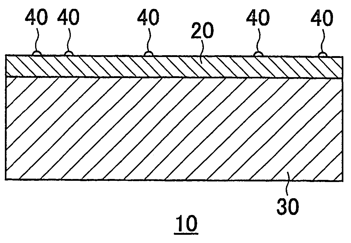
[0030]The friction mating member of the Example in accordance with the invention was fabricated from a base member having a ground surface finished by polishing with a polishing compound. The ground and polished surface of the base member was coated with a hard coating of a composite material containing amorphous carbon and tungsten carbide.

[0031]In Comparative example 1, a friction mating member in was fabricated by coating a surface of a base member with a chromium or TiN coating.

[0032]In Comparative example 2, a friction mating member the ratio of the area of semispherical protrusions to the area of the surface of a coating applied to the surface of a base member was small.

[0033]In Comparative example 3, a friction mating member included a base member having a high degree of surface roughness.

[0034]In Comparative example 4, the friction member, which was a currently mass-produced friction mating member, was made simply by grinding a surface of a base member, with no application o...


PUM

PropertyMeasurementUnit
surface roughness Raaaaaaaaaaa
diametersaaaaaaaaaa

Abstract

A friction mating member is fabricated by providing a surface of a base member with a hard coating having a load point displacement characteristic in which the elastic range, that is, the ratio of elastic deformation to maximum indentation depth, is at least 50% in a load range from 1 to 50 mN. The friction mating member is capable of coping with both an increasing friction coefficient in a high-speed range and decreasing friction coefficient in a low-speed range, without being affected by the type and deterioration of the lubricating oil. The friction mating member maintains an m-V characteristic having a positive gradient over a long period of use. Thus, the friction mating member solves problems attributable to noise and vibration.

Description

FIELD OF THE INVENTION[0001]This invention relates to a friction mating member, i.e., a contact member, for an oil-immersed friction device included in a power transmission mechanism for power transmission or power interception. More specifically, the invention relates to a contact part, such as a separator plate in a wet frictional interlocking mechanism, such as a wet-type, multiple-disc clutch, a multiple-disc brake included in an automatic transmission, a friction mating member, such as a torque converter cover included in a lock-up clutch, or a drum of a band brake.BACKGROUND OF THE INVENTION[0002]An automotive automatic transmission includes a multiple-disc clutch, provided with alternately arranged friction discs and separator plates, and immersed in an automatic transmission fluid (ATF) serving as a lubricating oil. The friction plates and the separator plates are frictionally engaged by being pressed against one another to transmit power, or disengaged, by removing engageme...

Claims


Application Information

Patent Timeline
Patent Type & Authority Patents(United States)
IPC IPC(8): B32B3/30F16D69/02C23C16/26F16D69/00C23C30/00F16D13/64F16D13/68F16D65/12
CPCF16D69/00F16D69/02F16D2069/002Y10T428/24355F16D2250/0038Y10T428/24479F16D2069/005
Inventor TAKAKURA, NORIOSANBONGI, YUZURUKAMEYA, SHINTARO
Owner DAINATSUKUSU
Why Eureka
Try Eureka