High-speed precision interrupted ultrasonic vibration cutting method

a cutting method and ultrasonic technology, applied in the field of high-speed precision interrupted ultrasonic cutting method, can solve the problems of limited application of ultrasonic vibration cutting and tool breakage, and achieve the effects of reducing cutting speed, and reducing cutting heat accumulation

Active Publication Date: 2017-04-13
BEIHANG UNIV
View PDF1 Cites 12 Cited by
  • Summary
  • Abstract
  • Description
  • Claims
  • Application Information

AI Technical Summary

Benefits of technology

[0028]① The critical cutting speed of the conventional ultrasonic vibration cutting method and the elliptical ultrasonic vibration cutting method is exceeded. Significant advantages of the conventional ultrasonic vibration cutting method and the elliptical ultrasonic vibration cutting method are realized at an extremely low cutting speed. However, the advantages of vibration cutting are still able to be obtained through a tool-workpiece periodical separation effect by an application of the transverse vibration or the vibration with the transverse component.
[0029]② The high speed range of the traditional cutting method is exceeded. During a traditional high-speed cutting process, the cutting heat accumulates severely due to a relative longer continuous contact time of the tool and the workpiece. Thus, the tool is worn rapidly and fails. In order to ensure an available tool life, a traditional cutting speed is generally in a low speed range of a corresponding material and machining process, leading that a machining efficiency is limited largely. However, a tool cutting heat accumulation is able to be avoided through the tool-workpiece periodical separation effect by the application of the transverse vibration or the vibration with the transverse component in the high-speed precision interrupted ultrasonic vibration cutting method. The cutting speed is able to reach two or three times of the traditional cutting speed, with a same tool life or surface quality, which enters the high speed range of the corresponding material and machining process and accordingly greatly enhances a cutting efficiency.
[0030]③ Referring to FIG. 4, the high-speed precision interrupted ultrasonic vibration cutting method is able to reduce the cutting force, wherein: compared to the traditional cutting method, a maximum reduction of a thrust cutting force is able to reach 50%.
[0031]④ Compared to the traditional cutting method, the cutting temperature of the high-speed precision interrupted ultrasonic vibration cutting method is reduced significantly. When the cutting fluid is applied, because of the interrupted separation effect, the cutting tool is fully cooled and lubricated in the noncutting stage, and a temperature reduction effect is more obvious.
[0032]⑤ Referring to FIG. 5, the high-speed precision interrupted ultrasonic vibration cutting method is able to defer a tool wear, and prolong the tool life. Compared to the traditional cutting method, in an experiment of turning titanium alloys with a linear cutting speed of 200 m / min a depth of cut of 0.05 mm a feedrate of 0.005 mm / r and a regular cutting fluid, the high-speed precision interrupted ultrasonic vibration cutting method is able to defer a tool wear speed significantly. When a wear criterion is defined as VB=0.3 and Ra=0.4, the tool life increases by three times.
[0033]⑥ Referring to FIG. 6, the high-speed precision interrupted ultrasonic vibration cutting method is able to enhance a cutting length. When the wear criterion for high precision cutting is defined as Ra=0.4, compared to the traditional cutting method, the cutting speed (efficiency) is doubled under a same cutting length condition while the cutting length is able to increase by three times under a same cutting speed condition.

Problems solved by technology

However, during the cutting process, the tool tip keeps engaged in the finished surface even though a separation effect between the tool tip and the chip exists, which enhances the friction between the cutting edge and the finished surface and causes tool breaking.
In conclusion, the application of ultrasonic vibration cutting is largely limited.

Method used


Image

  • High-speed precision interrupted ultrasonic vibration cutting method
  • High-speed precision interrupted ultrasonic vibration cutting method
  • High-speed precision interrupted ultrasonic vibration cutting method

Examples


Embodiment Construction

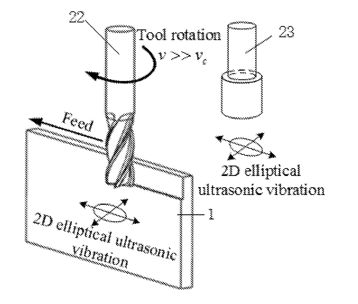
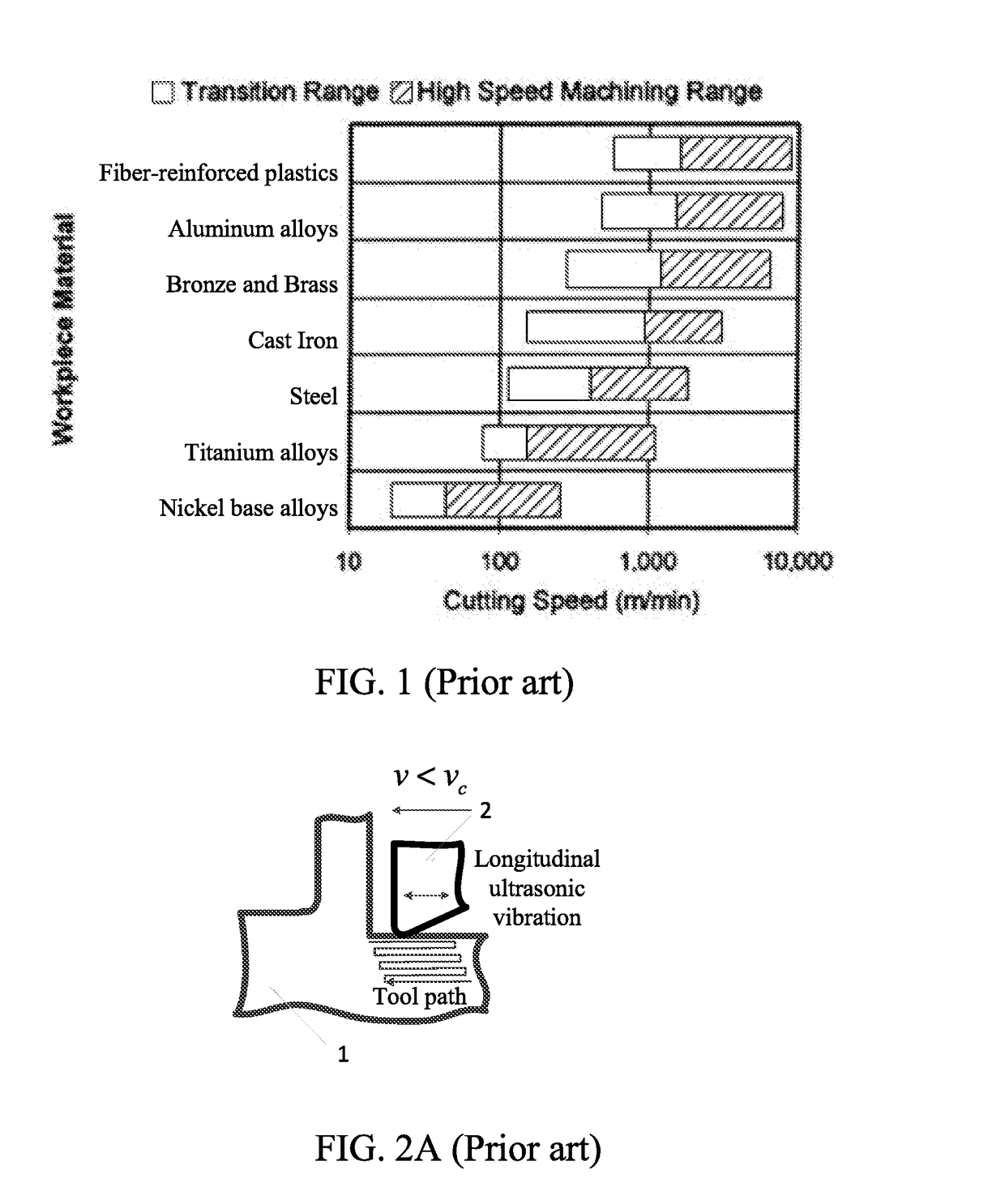
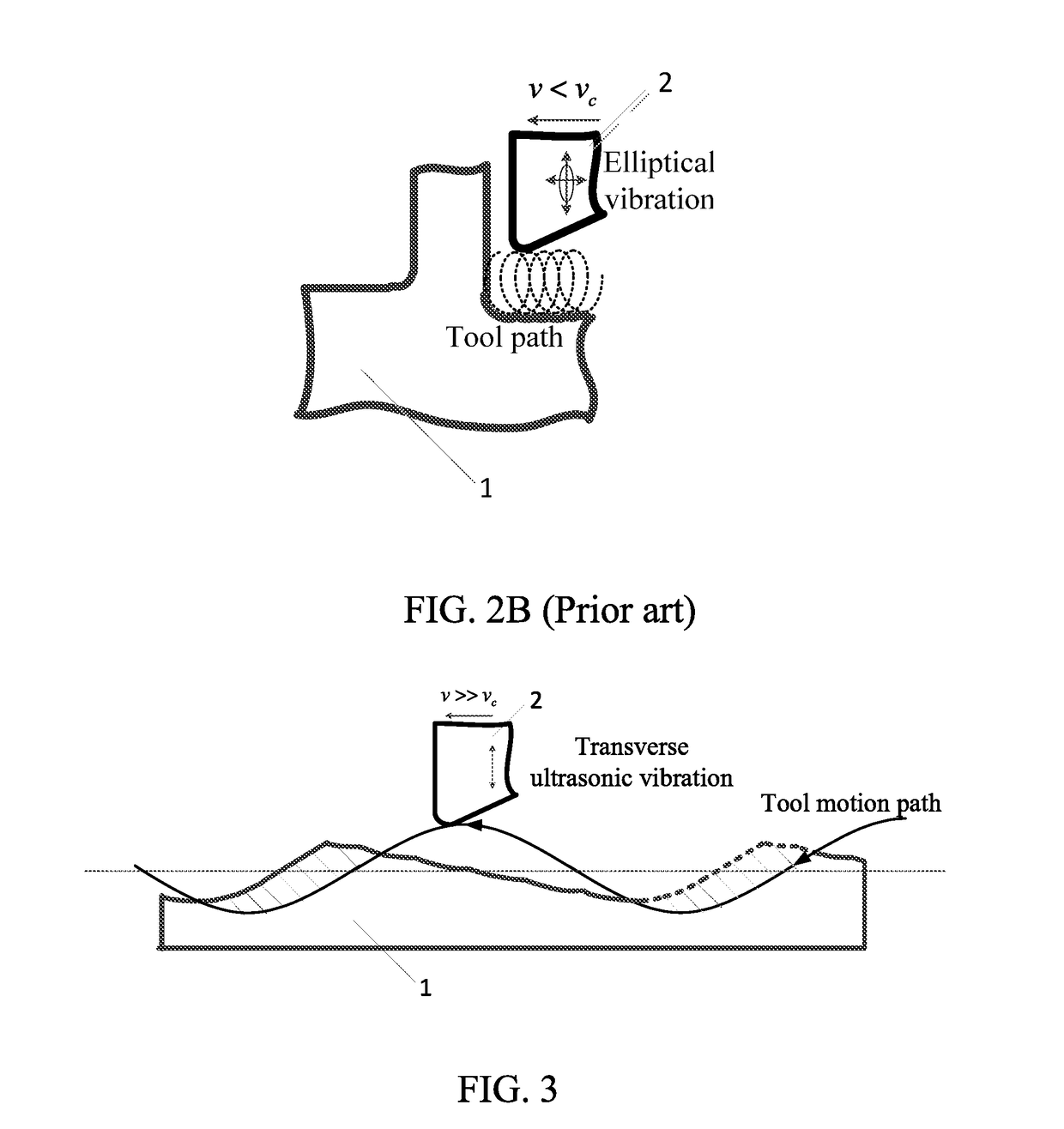
[0053]According to preferred embodiments of the present invention, a high-speed precision interrupted ultrasonic vibration cutting method is provided, wherein a principal diagram thereof is showed in FIG. 3 and FIG. 3A, and a cutting surface profile thereof is showed in FIG. 3B. Different from a conventional ultrasonic vibration cutting method showed in FIG. 2A and an elliptical ultrasonic vibration cutting method showed in FIG. 2B, the present invention has several advantages which are respectively showed in FIG. 4, FIG. 5, and FIG. 6, and enables a cutting speed to exceed a high speed range of a traditional cutting method showed in FIG. 1. A flow chart of the cutting method of the present invention is showed in FIG. 12.

[0054]First preferred embodiment: High-speed interrupted ultrasonic vibration turning

[0055]Turning is a cutting process, which is for narrowing an outer diameter or an end surface of a circular profile. An application range of turning is generally from semi-roughing...


PUM

PropertyMeasurementUnit
cutting speedaaaaaaaaaa
speedaaaaaaaaaa
cutting speedaaaaaaaaaa

Abstract

A high-speed precision interrupted ultrasonic vibration cutting method includes steps of: (1) installing an ultrasonic vibration apparatus on a machine tool, and stimulating a cutting tool to generate a transverse vibration, so as to realize varieties of machining processes; (2) realizing an interrupted cutting process by setting cutting parameters and vibration parameters to satisfy an interrupted cutting conditions; and (3) turning on the ultrasonic vibration apparatus and the machine tool, and starting a high-speed precision interrupted ultrasonic vibration cutting process. High-speed precision interrupted ultrasonic vibration cutting is able to be realized through the above steps during machining of difficult-to-machine materials in aviation and aerospace fields. A cutting speed is enhanced significantly, and exceeds a critical cutting speed of a conventional ultrasonic vibration cutting method and an elliptical ultrasonic vibration cutting method and even a high speed range of a traditional cutting method.

Description

CROSS REFERENCE OF RELATED APPLICATION[0001]The application claims priority under 35 U.S.C. 119(a-d) to CN 201610453083.9, filed Jun. 21, 2016.BACKGROUND OF THE PRESENT INVENTION[0002]Field of Invention[0003]The present invention relates to a high-speed precision interrupted ultrasonic vibration cutting method. By imparting ultrasonic vibration to a cutting tool through interrupted ultrasonic cutting during a whole cutting process, with reasonable set cutting parameters and vibration parameters, a workpiece is accomplished. An ultrasonic separation effect, which occurs during the cutting process, is able to realize precision machining in a high cutting speed.[0004]Description of Related Arts[0005]A high-speed cutting technology is an advanced machining technology having higher efficiency. Compared to a traditional cutting technology, the high-speed cutting technology obtains a much higher cutting speed. Non-ferrous metal, cast iron, steel, fiber reinforced composite material and nea...

Claims


Application Information

Patent Timeline
Patent Type & Authority Applications(United States)
IPC IPC(8): B23B37/00B23C9/00B23B29/12B24B1/04
CPCB23B37/00B24B1/04B23C9/005B23B2220/36B23B2215/04B23C2215/04B23C2220/44B23B29/125B23B2265/16B23C3/00B23C2265/16B23C2270/10B23D75/00
Inventor ZHANG, DEYUANZHANG, XIANGYUSUI, HEXIN, WENLONGJIANG, XINGGANG
Owner BEIHANG UNIV
Why Eureka
Try Eureka