Substrate Forming Method

A molding method and substrate technology, applied in the direction of structural parts, battery pack parts, manufacturing tools, etc., can solve the problems of increasing the cost of tab cutting and molding, slow cutting speed, and easy wear of the knife mold, so as to improve the cutting quality, Increased cutting speed and improved molding quality

Active Publication Date: 2018-10-26
NINGDE AMPEREX TECH
View PDF4 Cites 0 Cited by
  • Summary
  • Abstract
  • Description
  • Claims
  • Application Information

AI Technical Summary

Problems solved by technology

[0004] At present, the commonly used cutting methods include laser cutting and die cutting after coating, but there are many problems in the two cutting methods. The main problem of die cutting is that the die is easy to wear, which increases the forming cost of tab cutting , the burrs of the pole piece after die-cutting are large and the efficiency is low, while laser cutting is generally carried out after coating. When cutting, it needs to cut at the edge of the coating, resulting in slow cutting speed and high cutting requirements. Energy, so cutting costs are relatively high

Method used


Image

  • Substrate Forming Method
  • Substrate Forming Method
  • Substrate Forming Method

Examples


Embodiment Construction

[0021] The substrate molding method according to the present invention will be described in detail below with reference to the accompanying drawings.

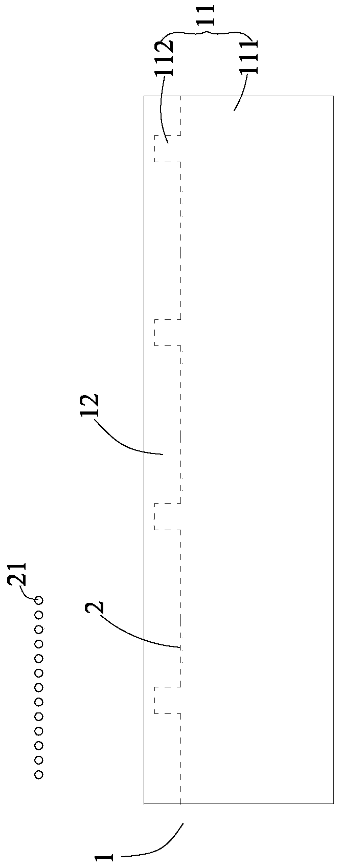
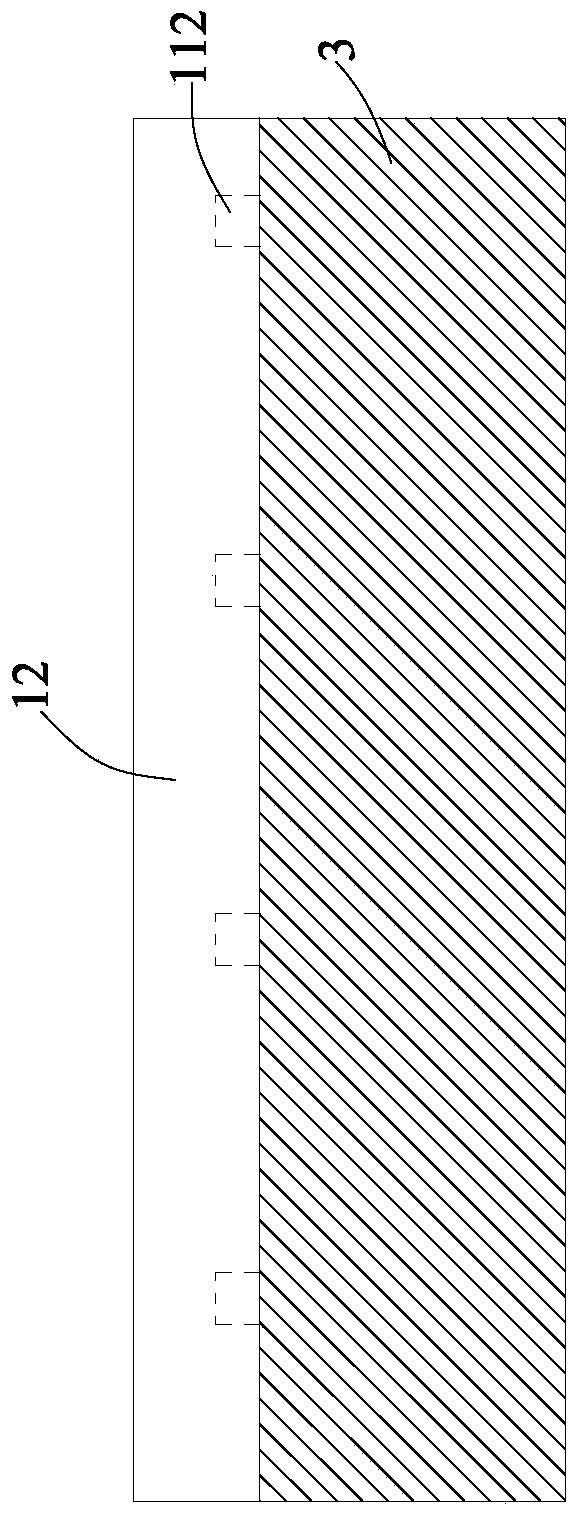
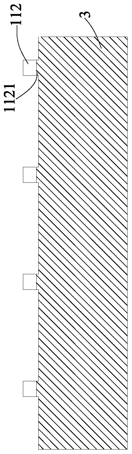
[0022] refer to Figure 1 to Figure 3 According to the substrate forming method of the present invention, the method includes steps: Step 1: During the conveyance of the substrate 1 after unwinding, use a laser to pre-cut the substrate 1 along the pre-cutting track, and the substrate 1 after the pre-cut is not cut. Cut off completely by laser and form pre-cutting slit 2 along pre-cutting track on base material 1, the base material 1 after the pre-cut forms the part 11 that is positioned at pre-cut slit 2 both sides and scrap part 12 (refer to figure 1 ); Step 2: in the conveying process of the base material 1 after pre-cutting, on at least one surface of the base material 1 (single side or both sides of the base material 1), the molding part formed after the base material 1 is pre-cut The side where 11 is located is coated wit...


PUM

PropertyMeasurementUnit
thicknessaaaaaaaaaa

Abstract

The invention provides a method for forming a substrate, which includes the steps: Step 1: During the conveyance of the unrolled substrate, use a laser to pre-cut the substrate along the pre-cutting track, and the pre-cut substrate is not It is completely cut off by the laser and forms a pre-cutting slit along the pre-cutting track on the base material. The pre-cut base material forms the forming part and the leftover part located on both sides of the pre-cutting slit; Step 2: After pre-cutting the base material During the conveying process of the substrate, coating is applied on at least one surface of the substrate on the side where the forming part formed after pre-cutting of the substrate is located and dried; and Step 3: coating the coated substrate During the winding process, along the pre-cut slit in step 1, the forming part of the base material and the leftover part are mechanically separated by pulling force, and the forming part coated with the coating is used as the base sheet. The substrate forming method of the present invention has the advantages of increased cutting speed, reduced burr size on the cut section, greatly reduced cost and the like.

Description

technical field [0001] The invention relates to the field of energy storage devices, in particular to a method for forming a substrate. Background technique [0002] Power lithium-ion batteries have received widespread attention because of their high energy density and environmental friendliness. They have been widely used in electric vehicles and hybrid vehicles. With the development of electric vehicle technology, lithium-ion batteries are widely used in the field of electric vehicles. applications are gaining more and more attention. [0003] The most important part in the production process of power lithium-ion batteries is pole piece forming. The existing process of tab forming is that the pole piece is coated and placed on a platform, and the required pole piece is directly cut by die-cutting. Slices die cut out. The so-called pole piece forming refers to the formation of tabs, that is, the tabs need to be cut out after the foil is coated. [0004] At present, the c...

Claims


Application Information

Patent Timeline
Patent Type & Authority Patents(China)
IPC IPC(8): H01M4/139H01M4/04H01M2/26B23K26/364H01M50/531
CPCH01M4/04H01M4/139H01M50/531Y02E60/10
Inventor 张玢方宏新何平赵义程文强
Owner NINGDE AMPEREX TECH
Why Eureka
Try Eureka