
Mechanism for tracking tainted data

a technology for tracking and data, applied in the field of data management, can solve problems such as attackers accessing unintended functionality

Inactive Publication Date: 2016-08-11
QUALCOMM INC
View PDF4 Cites 6 Cited by
  • Summary
  • Abstract
  • Description
  • Claims
  • Application Information

AI Technical Summary

Benefits of technology

The patent text describes a system that can detect when someone passes through data that has been tainted (which means it has been infected with malicious software). If this happens, the system will alert and prevent the tainted data from causing damage to the operation that is using it. This helps to keep things running smoothly and prevents sensitive information from being compromised.

Problems solved by technology

There is a large class of security vulnerability which is typified by trusting incorrectly vetted external inputs, allowing attackers to access unintended functionality.

Method used


Image

  • Mechanism for tracking tainted data
  • Mechanism for tracking tainted data
  • Mechanism for tracking tainted data

Examples


example electronic

Device

[0076]FIG. 10 is an illustration of an apparatus 1000 configured to support data tracking operations according to one or more aspects of the disclosure. The apparatus 1000 includes a communication interface 1002, a storage medium 1004, a user interface 1006, a memory device 1008, and a processing circuit 1010.

[0077]These components can be coupled to and / or placed in electrical communication with one another via a signaling bus or other suitable component, represented generally by the connection lines in FIG. 10. The signaling bus may include any number of interconnecting buses and bridges depending on the specific application of the processing circuit 1010 and the overall design constraints. The signaling bus links together various circuits such that each of the communication interface 1002, the storage medium 1004, the user interface 1006, and the memory device 1008 are coupled to and / or in electrical communication with the processing circuit 1010. The signaling bus may also ...

example processes

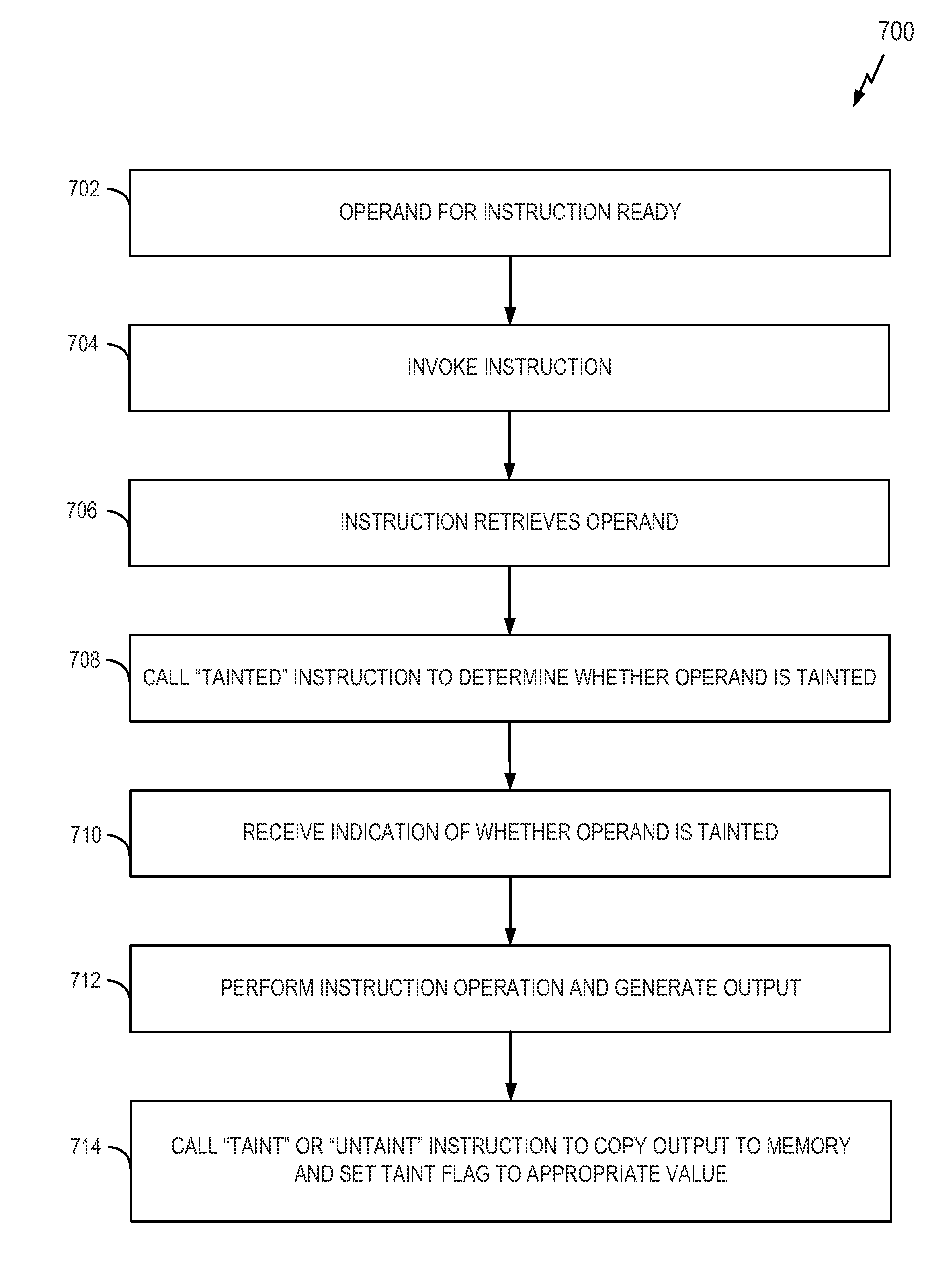
[0095]FIG. 11 illustrates a process 1100 for data tracking in accordance with some aspects of the disclosure. The process 1100 may take place within a processing circuit (e.g., the processing circuit 1010 of FIG. 10), which may be located in an electronic device or some other suitable apparatus. Of course, in various aspects within the scope of the disclosure, the process 1100 may be implemented by any suitable apparatus capable of supporting data tracking operations. In some aspects, the method is implemented in a Data Flow computer architecture (e.g., an EDGE architecture).

[0096]At block 1102, first data is received from a first memory location. In some aspects, the first physical memory location is a physical register, a page of a physical memory, or a physical input / output (I / O) port.

[0097]At block 1104, a determination is made as to whether the first data is tainted. This determination may be based on a first indication (e.g., a taint flag) stored for the first physical memory ...


PUM


Abstract

The disclosure relates in some aspects to protecting systems and data from maliciously caused destruction. Data integrity is maintained by monitoring data to detect and prevent potential attacks. A mechanism for tracking whether data is tainted is implemented in a Data Flow computer architecture or some other suitable architecture. In some aspects, a taint checking mechanism is implemented within a register file, memory management, and an instruction set of such an architecture. To this end, an indication of whether the data stored in a given physical memory location is tainted is stored along with the physical memory location. For example, a register can include a bit for a corresponding taint flag, a memory page can include a bit for a corresponding taint flag, and an input / output (I / O) port can include a bit for a corresponding taint flag.

Description

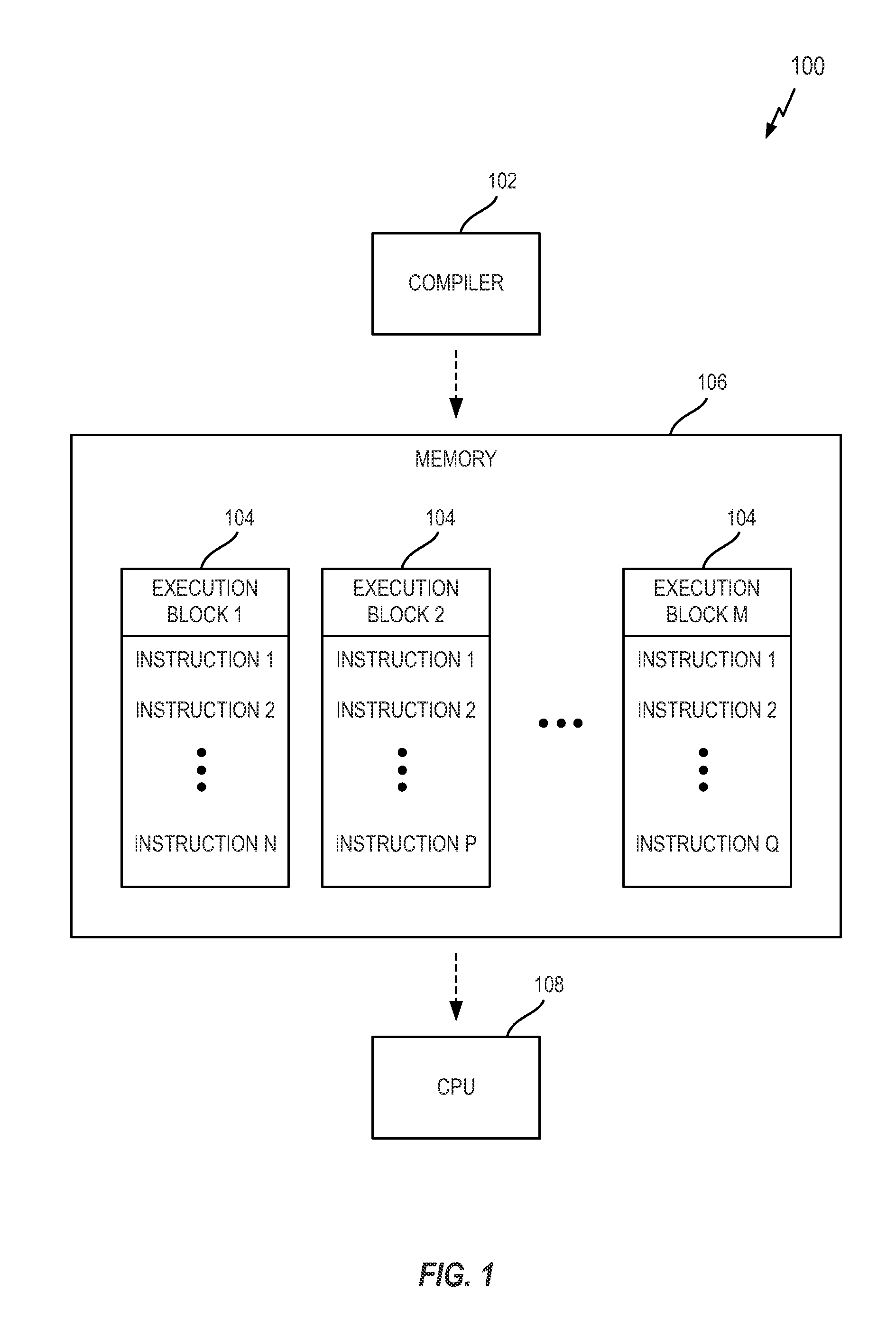
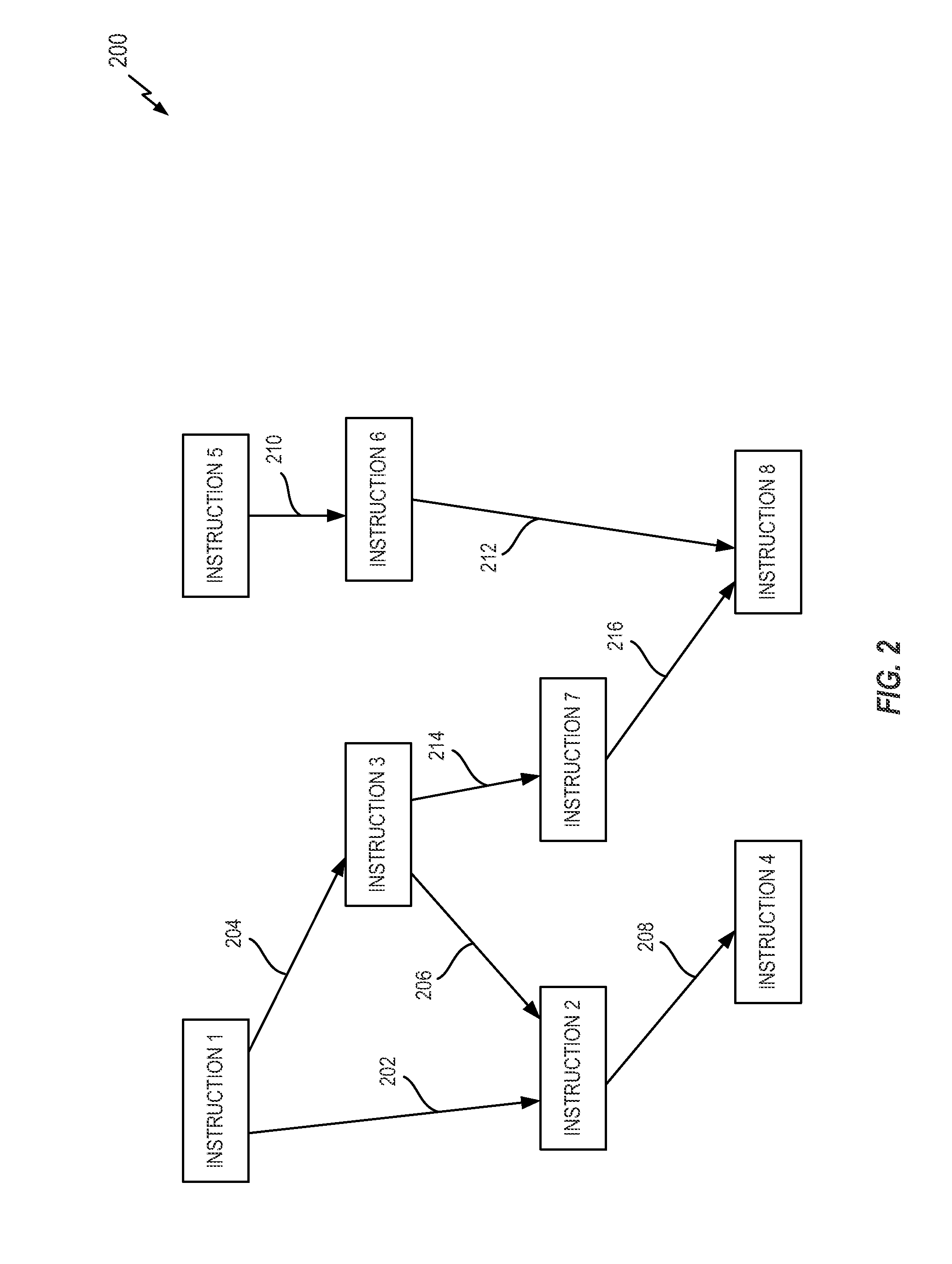
BACKGROUND[0001]1. Field of the Disclosure[0002]Aspects of the disclosure relate generally to data management, and more specifically, but not exclusively, to tracking tainted data.[0003]2. Description of Related Art[0004]In computer architectures, there is a need to ensure that data used by a computer is not compromised (e.g., by a hacker, a malicious program, etc.). Data to be protected includes data stored in memory and registers.[0005]A Data Flow computer architecture such as an EDGE (Explicit Data Graph Execution) architecture may explicitly encode data dependencies between operations in machine instructions. EDGE architectures (such as Microsoft® E2) group instructions into execution blocks of (for example) up to 128 instructions. Stores and loads from registers are typically used to communicate values between different execution blocks.[0006]There is a large class of security vulnerability which is typified by trusting incorrectly vetted external inputs, allowing attackers to ...

Claims


Application Information

Patent Timeline
Patent Type & Authority Applications(United States)
IPC IPC(8): G06F21/55G06F21/60
CPCG06F21/552G06F21/52G06F2221/034G06F21/60C09J4/06C09J11/06C09J7/10C09J7/30G02B5/30G09F9/30G06F9/38
Inventor PADDON, MICHAEL WILLIAMDUGGAN, MATTHEW CHRISTIANBROWN, CRAIGTARUI, KENTO
Owner QUALCOMM INC
Learn More