
Method for transferring a useful layer

Active Publication Date: 2016-08-11
S O I TEC SILICON ON INSULATOR THECHNOLOGIES
View PDF5 Cites 9 Cited by
  • Summary
  • Abstract
  • Description
  • Claims
  • Application Information

AI Technical Summary

Benefits of technology

The patent describes a method for treating a material using thermal fracture. The method includes a step to reduce the adhesion between the material and the surface it is attached to. This adhesion weakening allows the fracture to occur using less thermal energy. The technical effect is that the method can create a more efficient and controlled fracture in the material.

Problems solved by technology

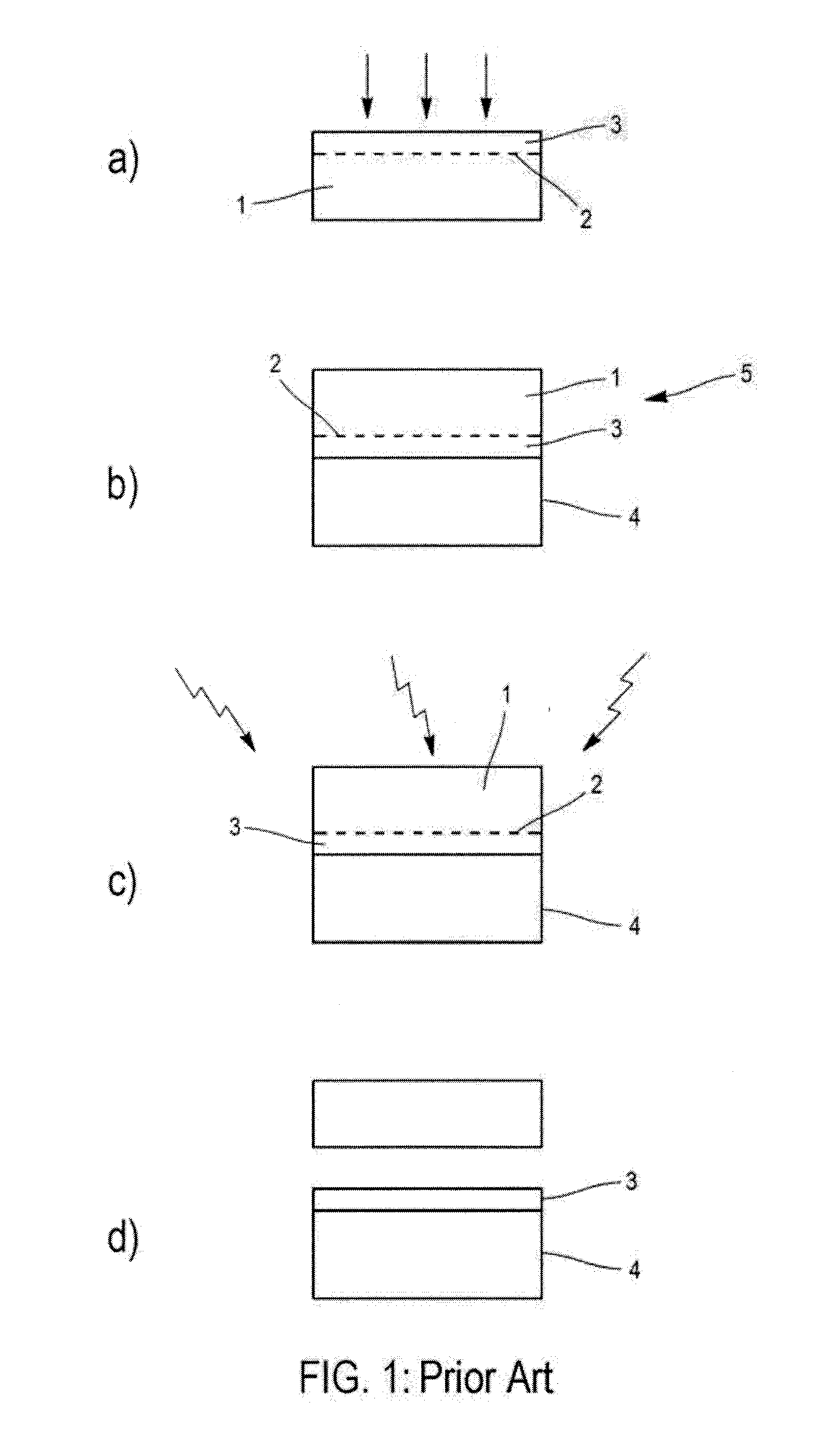
The thickness of the useful layer 4 is not perfectly uniform after the fracture step.
This approach however has the drawback of excessively lengthening the duration of the thermal embrittlement treatment, which is not favorable for the industrial exploitation of the method.
In some cases, it turns out not to be possible to cause the initiation of the fracture, even for a very long treatment time, when the temperature of the thermal treatment is below a threshold temperature.
However, this approach also has limitations.
It requires the development of equipment dedicated to this mechanical fracture step, which can be complex and costly notably where the assembly to be fractured needs to be maintained at temperature.
In addition, this fracturing operation is likely to cause defects around the periphery of the useful layer 3 or of the carrier 4, linked to the insertion of the mechanical element at the mounting interface of the assembly to be fractured 5.
This control is particularly tricky when the substrates are processed in batches, since each assembly of the batch to be fractured 5 can have a sensitivity to the thermal embrittlement treatment that is slightly different.

Method used


Image

  • Method for transferring a useful layer
  • Method for transferring a useful layer
  • Method for transferring a useful layer

Examples


example 1

[0105]A batch composed of 25 assemblies to be fractured 5, all identical to that of the example 1, is placed in an oven, in an atmosphere of nitrogen, having a temperature of 350° C., for 2 hours.

[0106]After the annealing, the fracture has not been initiated and the batch is removed from the oven and placed at ambient temperature in a wet atmosphere (45% humidity) for 1 hour.

[0107]The batch is subsequently placed in the oven at 250° for 2 hours. After this annealing, it is observed that all the wafers have spontaneously fractured.

[0108]Furthermore, the surface states of the useful layers are analyzed and exhibit thickness variations whose maximum amplitude over a wafer is less than 0.2 nm.

example 2

[0109]The experiment in the example 2 is reproduced, but between the two annealing steps the assemblies to be fractured 5 are exposed to a chemical attack of the wafer edge with a solution composed of water and of HF diluted to 10%, instead of the processing in the wet atmosphere.

[0110]The measurements performed on the useful layers 3 are identical to those in the example 1.

example 3

[0111]A batch of substrates to be fractured 5 is prepared in a similar manner to the two preceding examples, and placed in an oven under an inert atmosphere at 350° for 2 hours.

[0112]Without interrupting this annealing process, the temperature is subsequently reduced to 250° and the annealing continued for two hours at this temperature. At the start of this phase at 250°, water in the form of steam is injected into the atmosphere of the oven.

[0113]After the annealing, it is observed that all the wafers have been fractured. The measurements of mean thicknesses and of non-uniformities performed on the useful layers are identical to that of the example 1 or 2.


PUM


Abstract

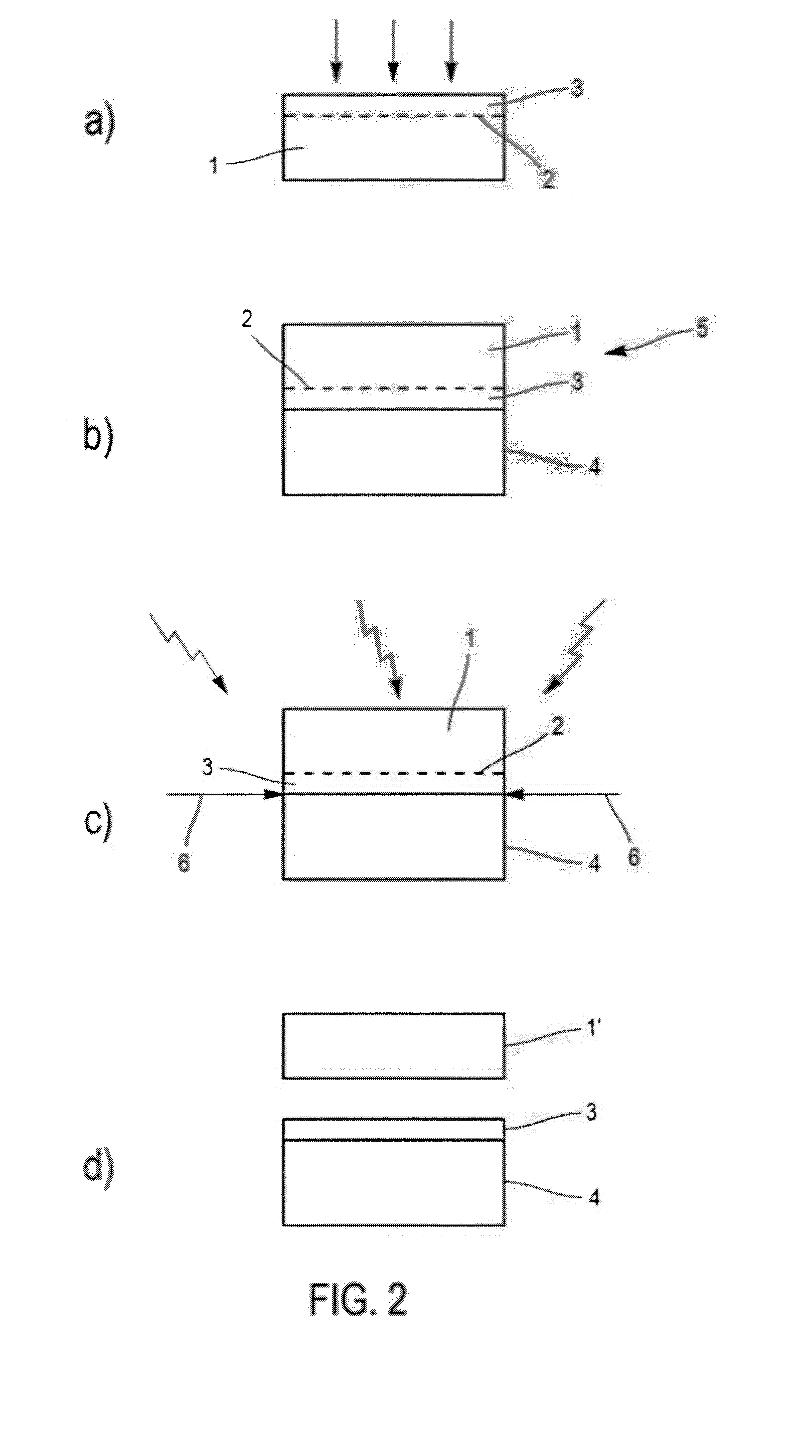
A method for transferring a useful layer onto a carrier comprises formation of an embrittlement plane by implantation of light species into a first substrate in such a manner as to define the bounds of a useful layer between this plane and a surface of the first substrate, mounting of the carrier onto the surface of the first substrate so as to form an assembly to be fractured, and thermal fracture treatment of the first substrate along the embrittlement plane in such a manner as to transfer the useful layer onto the support. During the thermal fracture treatment, the degree of peripheral adhesion is reduced at the interface between the carrier and the first substrate.

Description

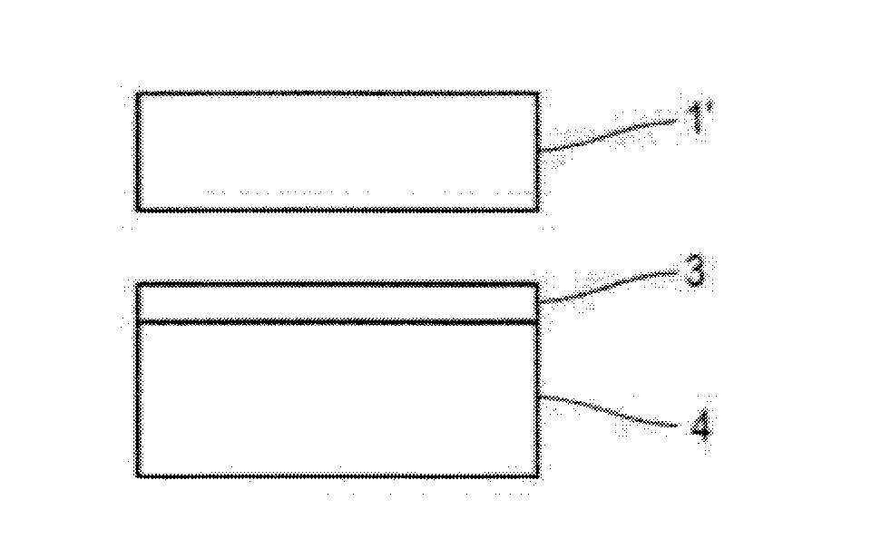
CROSS-REFERENCE TO RELATED APPLICATION[0001]Pursuant to 35 U.S.C. §119(a), this application claims the benefit of the filing date of French Patent Application Serial No. 1551046, filed Feb. 10, 2015, for “Method for Transferring a Useful Layer,” the contents of which are incorporated herein in their entirety by this reference.TECHNICAL FIELD[0002]The present disclosure relates to a method for transferring a useful layer onto a carrier substrate.BACKGROUND[0003]A method is known from the prior art for transferring a useful layer 3 onto a carrier substrate 4, shown in FIG. 1, this method comprising the following main steps:[0004]in a step a), the formation of an embrittlement plane 2 by implantation of light species into a first substrate 1 in such a manner as to define the boundaries of a useful layer 3 between this plane and a surface of the first substrate;[0005]in a step b), the application of the carrier 4 onto the surface of the first substrate 1 in order to form an assembly to ...

Claims


Application Information

Patent Timeline
IPC IPC(8): H01L21/762H01L21/324H01L21/265
CPCH01L21/26506H01L21/76254H01L21/324H01L21/185
Inventor LANDRU, DIDIERKONONCHUK, OLEGBEN MOHAMED, NADIA
Owner S O I TEC SILICON ON INSULATOR THECHNOLOGIES
Learn More