Air-cooled engine and engine working machine

a technology of working machine and air-cooled engine, which is applied in the direction of engines, machines/engines, mechanical apparatus, etc., can solve the problems of remarkably deteriorating product value and likely heat damage to the muffler cover 136, and achieve the effect of reducing the heat damage of the second muffler cover

Inactive Publication Date: 2016-08-18
KOKI HLDG CO LTD
View PDF3 Cites 8 Cited by
  • Summary
  • Abstract
  • Description
  • Claims
  • Application Information

AI Technical Summary

Benefits of technology

[0008]A small-sized air-cooled engine includes a first muffler cover that covers at least some of a muffler through a clearance and a second muffler cover that covers at least some of the first muffler cover through a clearance. A muffler cooling room is formed by the first muffler cover and the second muffler cover, and some of cooling air generated by a cooling fan is supplied to the muffler cooling room. Since the cooling air is supplied to at least one of a first space between the muffler and the first muffler cover and a second space between the first muffler cover and the second muffler cover, the muffler, the first muffler cover and the second muffler cover can be cooled by the cooling air, while the second muffler cover is protected from radiation heat by the muffler. Since the cooling air is guided in an exhaust direction of exhaust gas from the muffler by an air guiding portion, it is possible to effectively reduce heat damages of the second muffler cover.

Problems solved by technology

Therefore, the muffler cover 136 is likely to receive heat damages such as erosion due to receiving radiation heat from the muffler and heat by natural convection.
In particular, in a visible region from the outside, the heat damages (such as burnt, discoloration and transformation) result in an appearance defect, therefore, there has been a problem that the product value is remarkably deteriorated.

Method used


Image

  • Air-cooled engine and engine working machine
  • Air-cooled engine and engine working machine
  • Air-cooled engine and engine working machine

Examples


Embodiment Construction

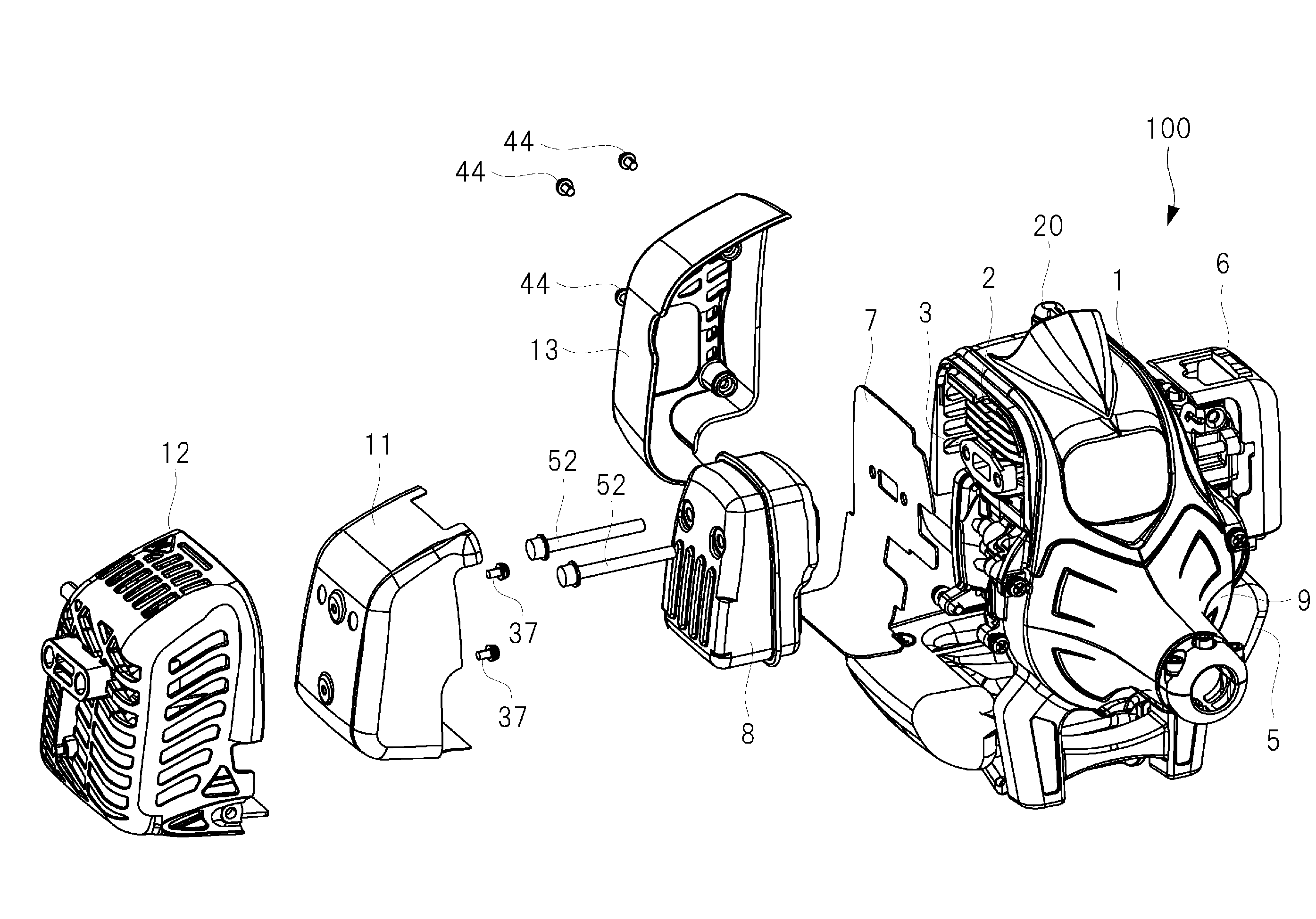
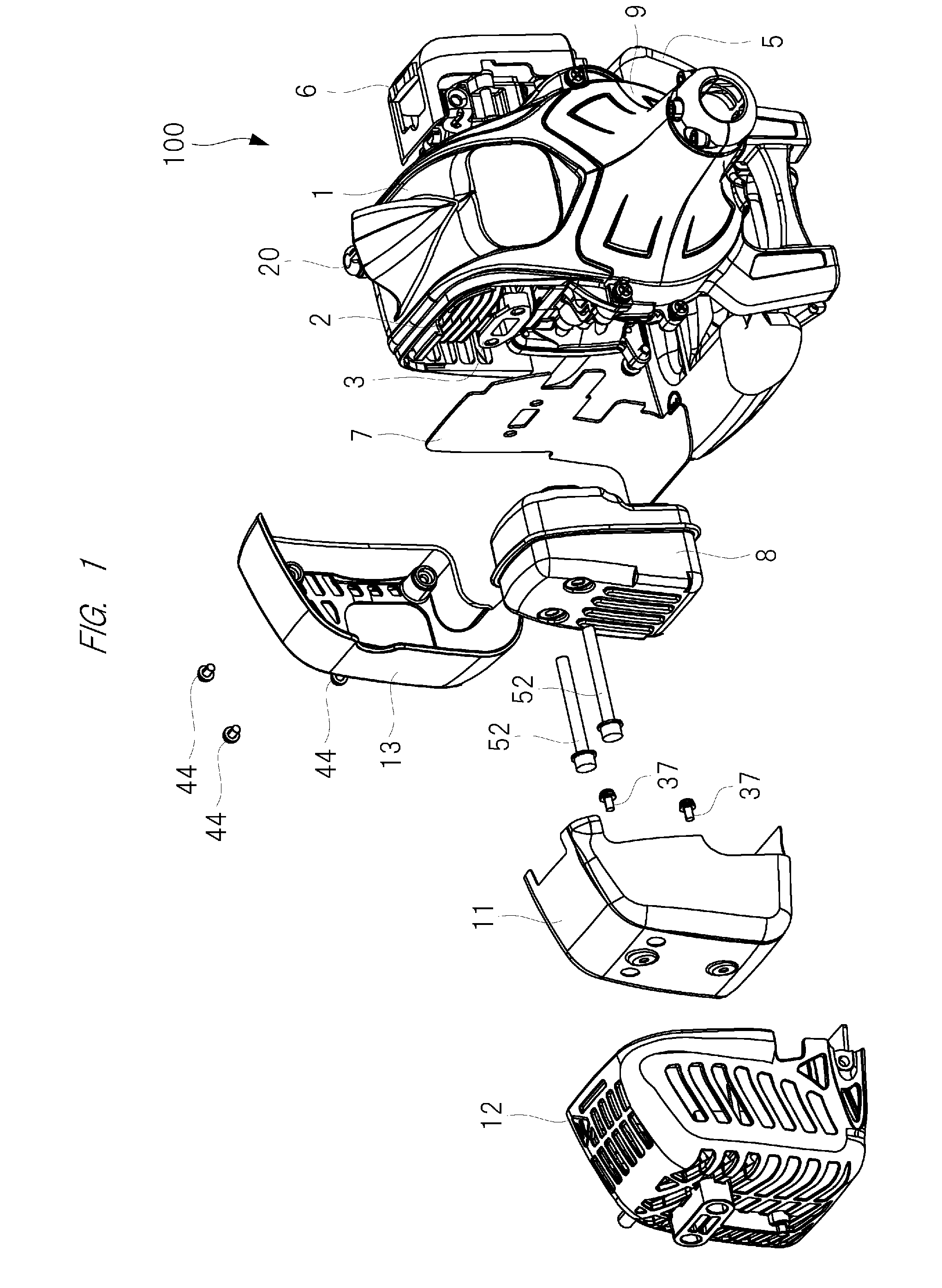
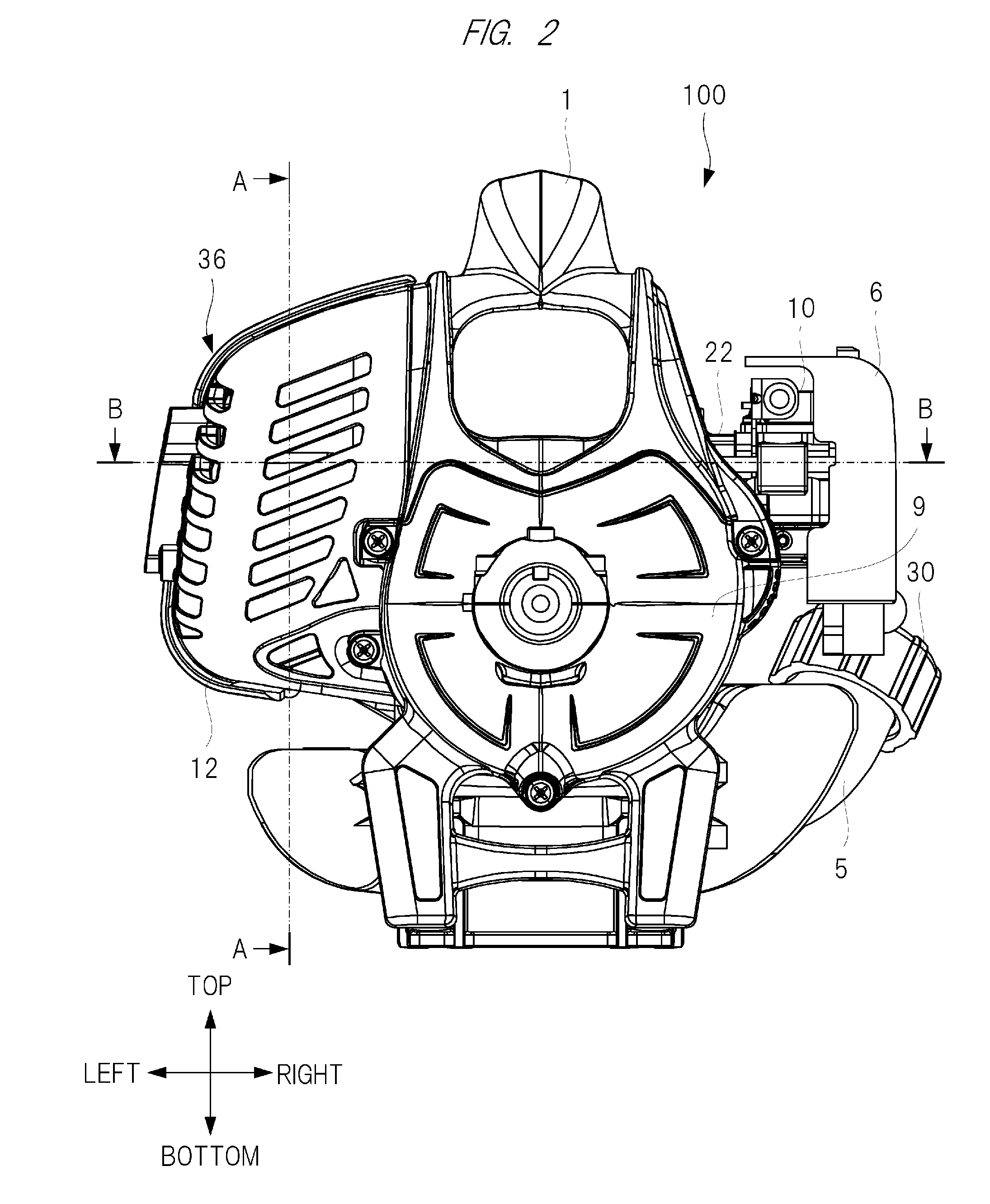
[0020]A structure of an air-cooled engine (engine) that is an embodiment of the present invention will be described. Herein, the air-cooled engine includes a two-stroke engine body having a cylinder, a crankcase, etc. and a cylinder cover that covers the cylinder, etc. In the engine body, a cooling fan is fixed to a driving shaft, and the cylinder is cooled in the cylinder cover by cooling air generated by rotation of the cooling fan. Further, in the cylinder, a plurality of radiation fins are formed on an outer surface of a cylinder portion formed in substantially a cylinder shape, and a combustion chamber is formed inside the cylinder portion.

[0021]This engine is applied to a portable working machine, such as a brush cutter and an air blower, carried by an operator, and the engine having the above structure is mounted in the engine working machine. Therefore, practically, a reducer, etc. for driving the engine working machine are connected to a driving shaft, and the structures fo...


PUM


Abstract

An air-cooled engine includes a muffler that is attached to an exhaust port of a cylinder and a fan case that houses a cooling fan, and a cylinder cooling room is formed by a cylinder cover that houses the cylinder. A muffler cooling room is formed by a first muffler cover that covers at least some of the muffler through a clearance and a second muffler cover that covers at least some of the first muffler cover through a clearance. Some of cooling air generated by the cooling fan is supplied to the muffler cooling room. The cooling air is supplied to at least one of a first space between the muffler and the first muffler cover and a second space between the first muffler cover and the second muffler cover.

Description

TECHNICAL FIELD[0001]The present invention mainly relates to an air-cooled engine used as a power source for a portable working machine such as a brush cutter and an air blower and for a working machine such as a generator, and in particular to a cooling structure for the air-cooled engine.BACKGROUND ART[0002]A small-sized air-cooled engine is widely used as a power source for a small-sized working machine such as a brush cutter and a chain saw. FIG. 11 is a perspective view illustrating an outline of a brush cutter 101 as one example of an engine working machine. As illustrated in FIG. 11, a small-sized air-cooled engine 110 is mounted in the engine working machine. The engine working machine includes a hollow main pipe 105, and an engine 110 is provided on one end of the main pipe 105, and a rotary blade 106 is provided on the other end of the main pipe 105. A driving shaft (not illustrated) is built inside the main pipe 105. By rotating the driving shaft by the engine 110, the ro...

Claims


Application Information

Patent Timeline
Patent Type & Authority Applications(United States)
IPC IPC(8): F01P1/06F01P5/04F02B75/02F01P1/02F01N1/14F02B63/02
CPCF01N3/10F02B2075/025F01N13/14F01N13/141F01N13/143F01P1/06F01N1/14F01N2230/04F01N2260/022F01N2260/20F01N2590/06F01P1/02F01P5/04F01P2001/023F02B63/02F02B75/02F01N13/002
Inventor ICHIHASHI, NAOTOKAWAGUCHI, TAKEFUMIKUGENUMA, JUN
Owner KOKI HLDG CO LTD
Why Eureka
Try Eureka