Motor with heat dissipation structure

a heat dissipation structure and motor technology, applied in the field of motors, can solve the problems of difficult accumulation of heat in the housing, and achieve the effect of increasing the service life and performance of the motor

Inactive Publication Date: 2016-08-18
CHOU
View PDF18 Cites 9 Cited by
  • Summary
  • Abstract
  • Description
  • Claims
  • Application Information

AI Technical Summary

Benefits of technology

[0005]One object of the present invention is to provide a motor with a heat dissipation structure, wherein the housing of the motor is provided with a hollow hood for collecting the air current generated by a cooling fan provided at a rotating shaft of the motor. The housing defines at least one upstream through hole and at least one downstream through hole. The hollow hood is mounted to the housing such that a head portion thereof is located above the upstream through hole. The air current can be effectively collected by the hollow hood to enter the housing via the upstream through hole and finally to go out of the housing via the downstream through hole, so that the heat generated by the rotor assembly in the housing can be quickly taken away. Thus, heat is not easy to accumulate in the housing, maximum power output of the motor can be achieved, and the performance and service life of the motor can be increased.

Problems solved by technology

Thus, heat is not easy to accumulate in the housing, maximum power output of the motor can be achieved, and the performance and service life of the motor can be increased.

Method used


Image

  • Motor with heat dissipation structure
  • Motor with heat dissipation structure
  • Motor with heat dissipation structure

Examples


Embodiment Construction

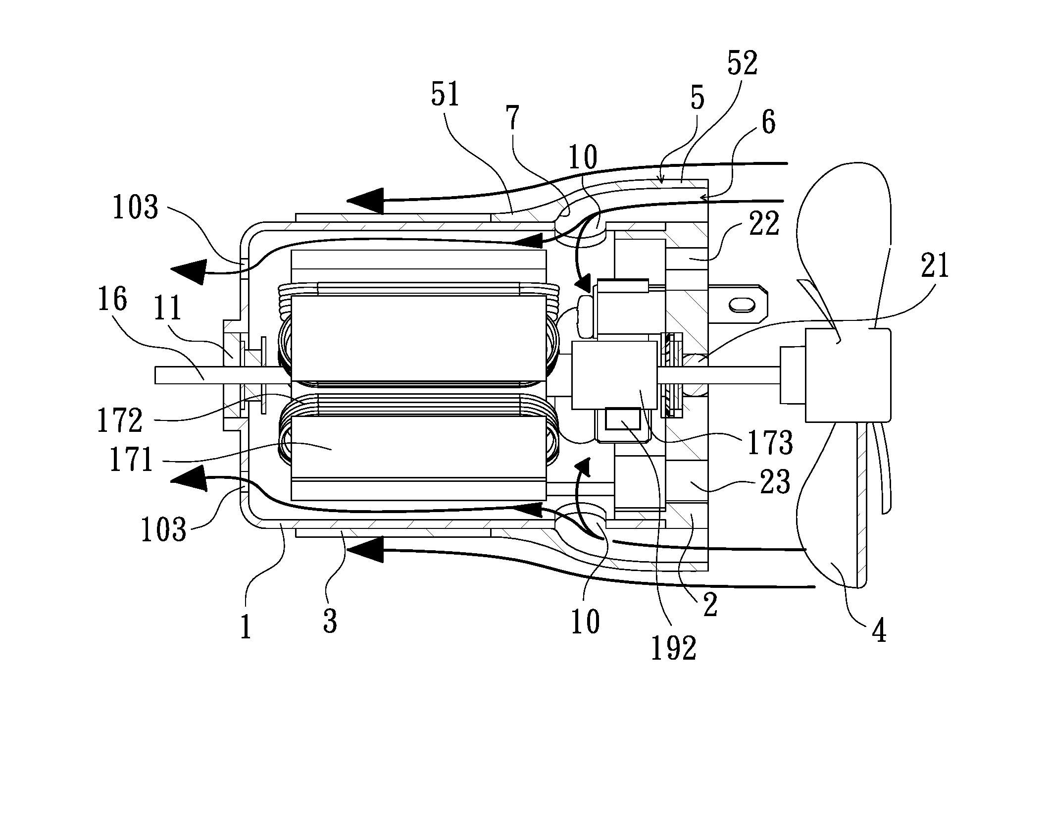
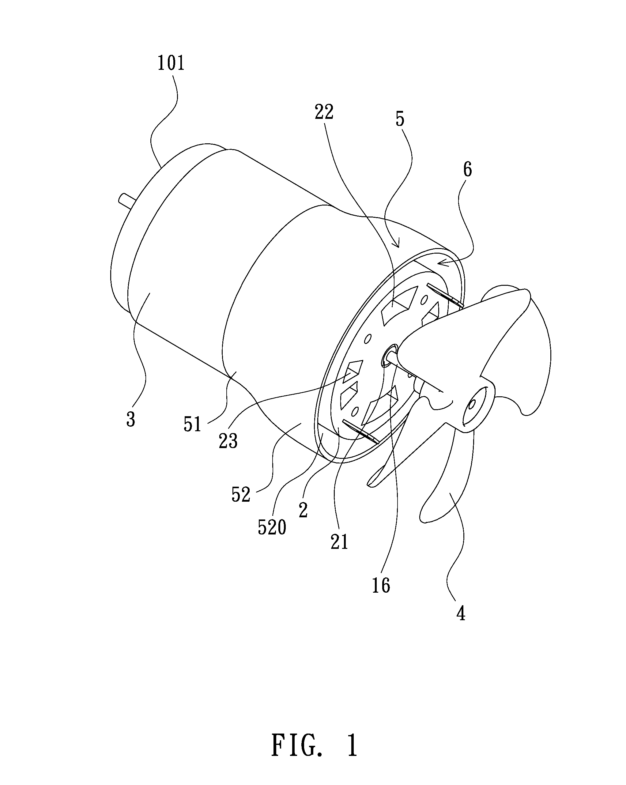
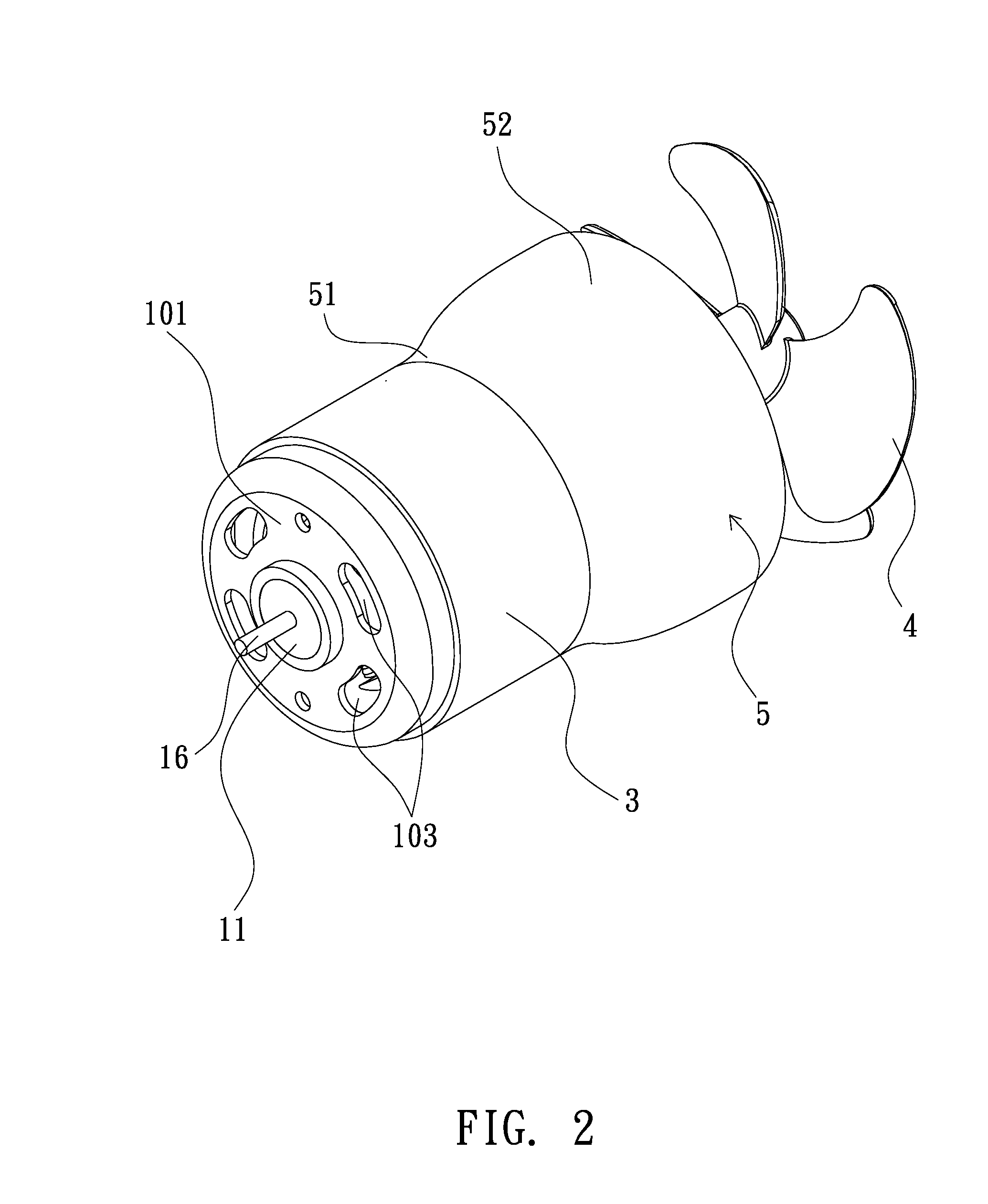
[0014]Since motors are commonly used devices, the principles of a motor's operation are not illustrated in the following paragraphs. However, basic elements of a motor will be described in this specification. Referring to FIGS. 1 through 7, a motor according to one embodiment of the present invention is shown, which includes a cylindrical housing 1, in which a rotor assembly and two opposite magnets 12 are provided. The rotor assembly includes a rotating shaft 16, an armature core formed by an iron core 171 wound with enameled wire 172, and a commutator 173. The two opposite magnets 12 are provided at an inner surface of the cylindrical housing 1. The housing 1 has a circumferential wall which terminates at a flat closure wall 101 (a front end of the motor). The flat closure wall 101 is provided with a first bearing 11 at its center and defines a plurality of downstream through holes 103 around the first bearing 11. A first end of the rotating shaft 16 is mounted to the first bearin...


PUM


Abstract

A motor includes a cylindrical housing, a cooling fan, and a rotating shaft. The cylindrical housing defines at least one upstream through hole at its circumferential wall. The cooling fan is mounted at the rotating shaft for generating airflow towards the cylindrical housing for dissipating the heat generated in the motor. The hollow hood is mounted to the cylindrical housing such that a head portion is located above the upstream through hole, thus defining an annular air-guiding channel therebetween, which can receive the airflow generated by the cooling fan and guide the airflow to enter the cylindrical housing via the upstream through holes, so that the heat generated therein can be dissipated effectively. Thus, heat is not easy to accumulate in the motor, and the performance and service life of the motor can be increased.

Description

(a) TECHNICAL FIELD OF THE INVENTION[0001]The present invention relates to a motor and, more particularly, to a motor with a heat dissipation structure capable of restraining temperature therein, wherein the motor is provided with a hollow hood at its housing for collecting the air current generated by a cooling fan provided at a rotating shaft of the motor, wherein one portion of the hollow hood is located above at least one upstream through hole of the motor's housing, so that the air current can quickly enter the housing via the upstream through hole to dissipate heat therein, and thus the performance and service life of the motor can be increased.(b) DESCRIPTION OF THE PRIOR ART[0002]Today, motors are widely used in industry for providing mechanical power. When a motor, irrespective of lower or high power, is running, the rotor assembly (including an armature core formed by an iron core wound with enameled wire, a commutator, a brush unit, etc.) and the magnets in the motor's ho...

Claims


Application Information

Patent Timeline
Patent Type & Authority Applications(United States)
IPC IPC(8): F04D29/58F04D29/32F04D29/053F04D25/06
CPCF04D25/06F04D29/053F04D29/325F04D29/5806H02K9/14F04D25/082H02K5/20H02K9/06F04D19/002H02K9/16H02K5/207
Inventor CHOU, WEN-SAN
Owner CHOU
Why Eureka
Try Eureka