Gas cylinder valve

Active Publication Date: 2016-08-18
LUXFER CANADA
View PDF9 Cites 3 Cited by
  • Summary
  • Abstract
  • Description
  • Claims
  • Application Information

AI Technical Summary

Benefits of technology

[0033]Advantages of the valve of this disclosure are that it is lightweight, robust, low torque, low leakage, indexable, and functions as a ¼ turn cylinder valve. When constructed of aluminum, the ball valve weighs about ½ of current valves. One suitable material for the housing of this disclosure is 6061 aluminum (compared to conventional stainless steel). Another advantage is that the valve of this disclosure exhibits very low torque to operate, on the order of 7% to 26% of current products. Yet another advantage is that the ball seals used in the valve of this disclosure actually survive the specified temperatures and pressures. In contrast, most current products fail their seals upon reaching 85° C. and full pressure. Another aspect is that the stem and bearing system of the present valve is installed from outside the valve. Current stems are inserted from a center of the valve. Indexable valve stud and jam nut of the present valve allow 370° rotational positioning of the valve. For example, the stud has 4.6 to 5.7 full threads engaging the valve head. That is, the valve head can be turned up to 370° to get it in the desired angular location and still have 4.6 full threads engaged. The head is then locked in place by the jam nut.
[0034]High technology bearing and seal polymeric materials of the present valve permit low torque, long life and

Problems solved by technology

A disadvantage with these valves, which are generally made of brass o

Method used


Image

  • Gas cylinder valve
  • Gas cylinder valve
  • Gas cylinder valve

Examples


Example

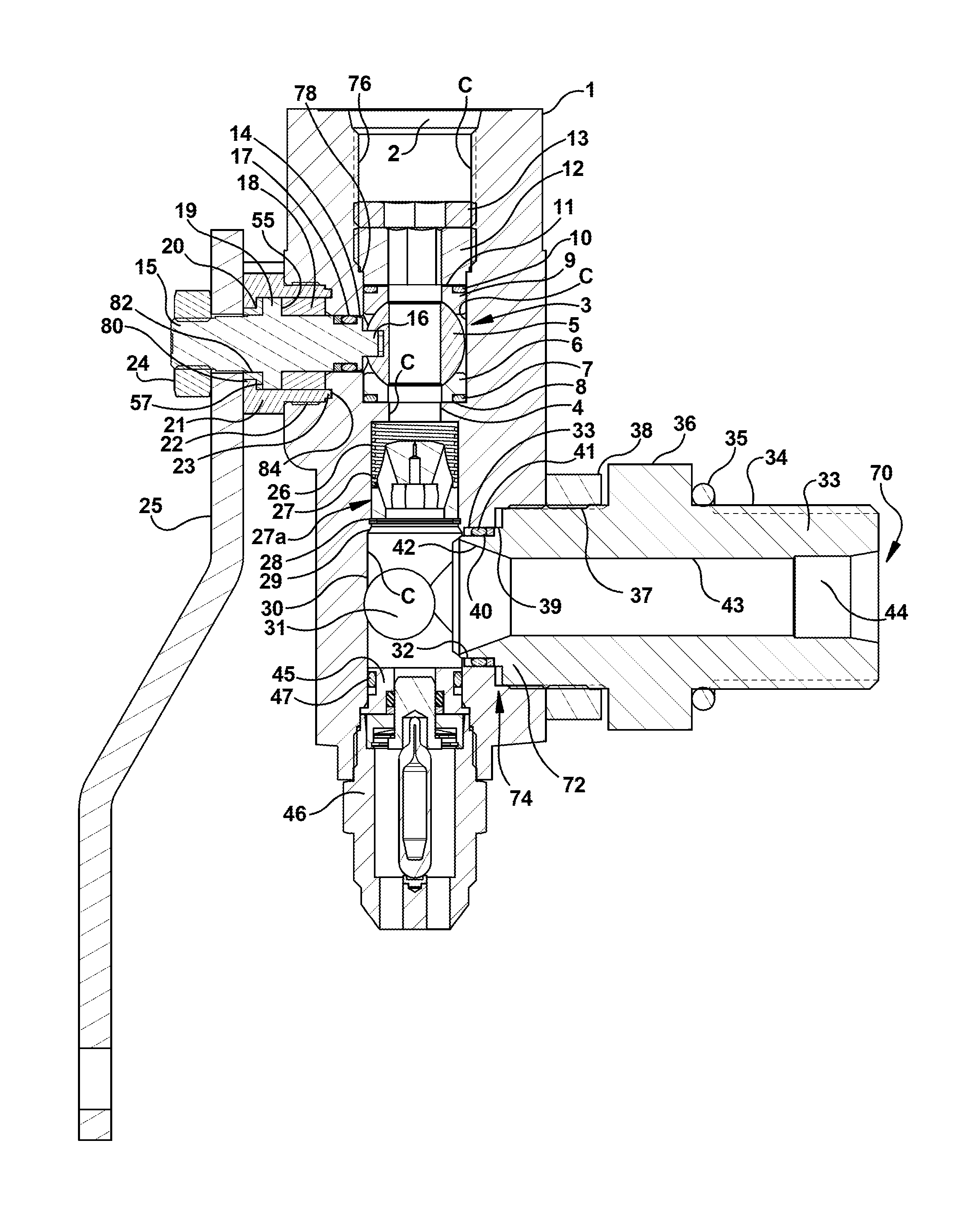
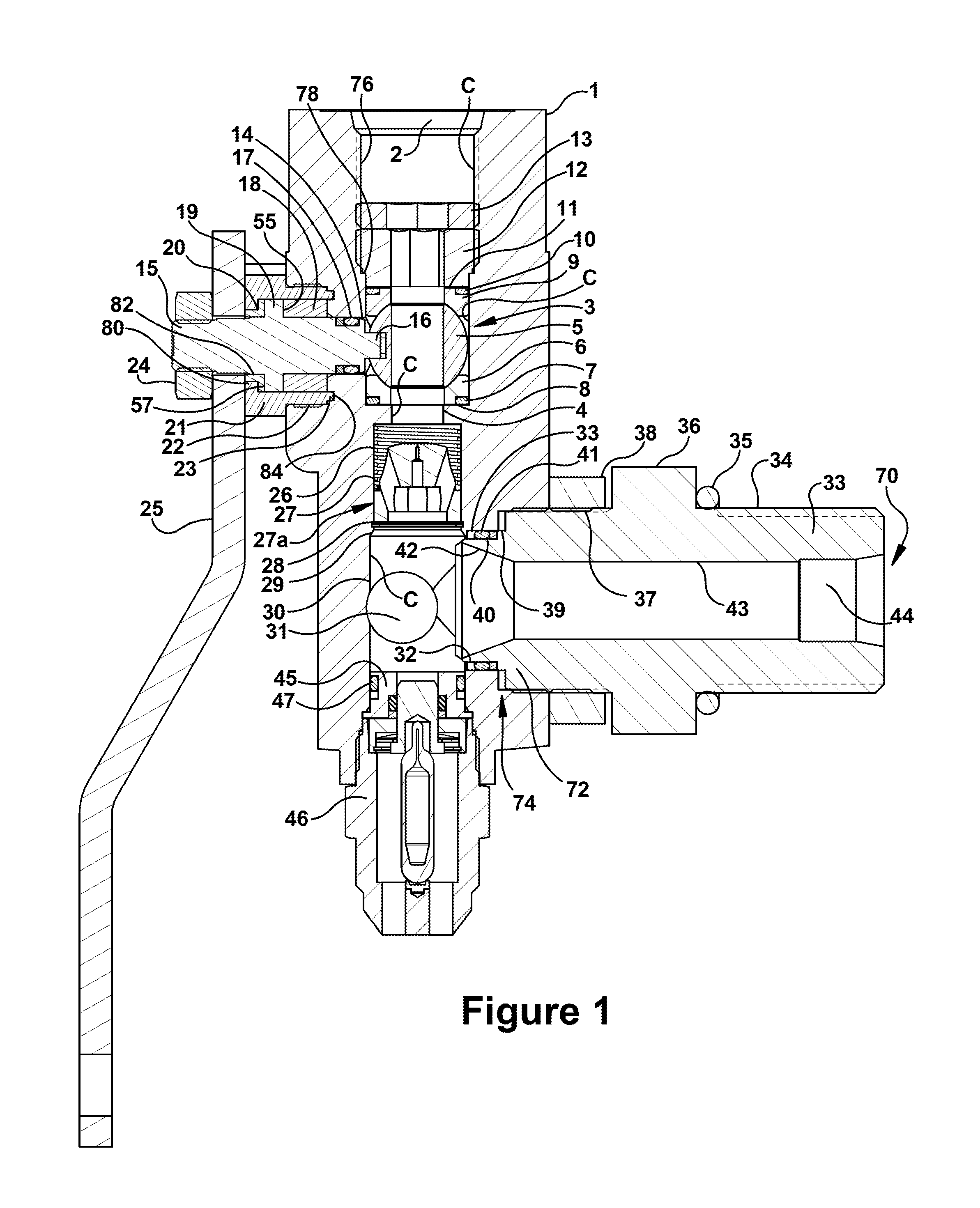
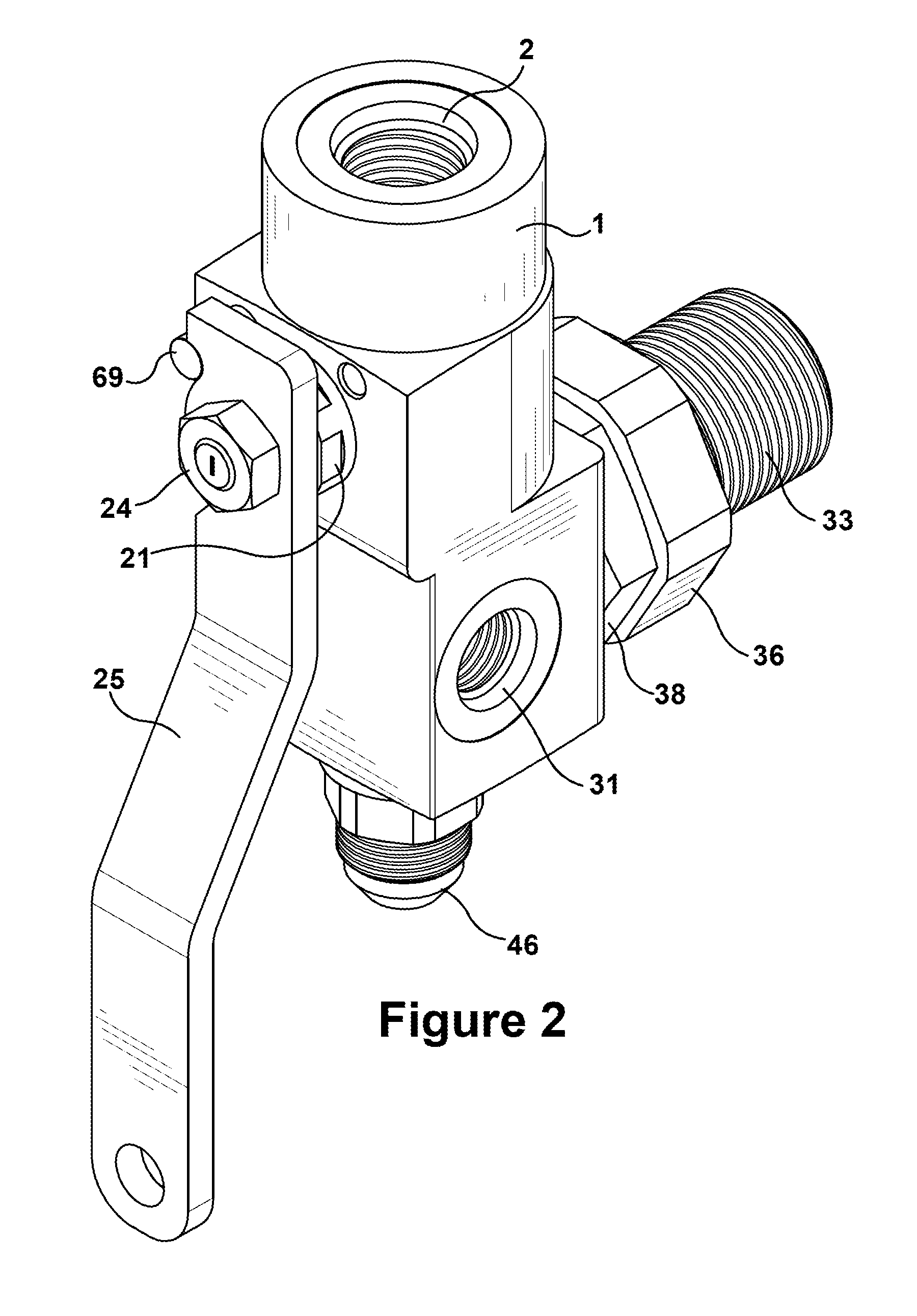
[0048]Referring to FIGS. 1 and 2, a housing or valve body 1 is in particular comprised of aluminum, for example, 6061 aluminum (or equivalent). The valve body is attached to an O-ring sealed, removable tube or threaded tube or stud 33 which mounts the valve into a mating high pressure container (e.g., a gas cylinder). The stud comprises a gas cylinder aperture 70 at its proximal end, a tube aperture 72 at its distal end for connection to a cylinder aperture 74 of the housing in order to provide fluid connection to the housing conduit C, and a tube conduit which provides fluid communication between the gas cylinder aperture and the tube aperture. In particular, the stud has an indexing feature allowing the valve body 1 to be rotated within a range (such as 370°) for optimal positioning. The stud 33 has exterior threads 34 at the proximal end portion of the stud which mate with or engage interior threads of the pressure cylinder. The same valve can be mounted to various cylinder necks...


PUM


Abstract

Disclosed is a valve for connection to a pressurized gas cylinder. The valve includes a housing including a gas cylinder aperture which is connectable to a gas cylinder, and a housing conduit which extends through the housing from the gas cylinder aperture to one or more inlet/outlet apertures so that the valve is capable of providing fluid communication between the gas cylinder through the housing conduit and the one or more inlet/outlet apertures. A flow control ball within the housing conduit is movable between open and closed positions. Ball seals have sealing surfaces corresponding to a shape of the flow control ball for substantially sealing the flow control ball in the housing conduit. Other features include components for mounting the ball seals though one of the inlet/outlet apertures; components for mounting a stem to the flow control ball including bearings; live ports; a tube which can be removably connectable from the rest of the housing; provision for receiving an EFV and/or a PRD in the valve housing; and at least one of the ball seals and stem bearings being comprised of special polymeric material including polyetherimide or polyaryletherketone.

Description

CROSS REFERENCE OF RELATED APPLICATIONS[0001]The present application is a continuation-in-part of U.S. patent application Ser. No. 14 / 600,567, filed Jan. 20, 2015, entitled “Gas Cylinder Valve”, naming inventor Stephen Alan Carter, the disclosure of which is incorporated herein by reference.TECHNICAL FIELD[0002]This disclosure relates to a valve for a pressurized gas cylinder.BACKGROUND[0003]In the field of high pressure gas cylinders, it is well-known to fit valves onto such cylinders in order to provide a closable opening to the cylinder. Such cylinders tend to contain gases such as natural gas or hydrogen, and can also be used to contain other gases such as nitrogen, helium, argon or air. The valve can be opened to allow either the filling or emptying of the gas cylinder, and then can be closed again once this operation is complete.[0004]A disadvantage with these valves, which are generally made of brass or steel, is the inefficiency of the flow of the gas through the valve. One ...

Claims


Application Information

Patent Timeline
IPC IPC(8): F16K27/06F16K5/06
CPCF16K27/067F16K5/0647F16K5/0694F16K5/0668F16K5/0642F16K5/0663F16K5/0684F17C2205/0332F17C2205/0385F17C2221/012F17C2221/033F17C2223/0123F17C2223/036Y10T137/87917Y02E60/32
Inventor CARTER, STEPHEN ALAN
Owner LUXFER CANADA
Why Eureka
Try Eureka