Integrated lens with multiple optical structures and/or surfaces, optical module and transceiver including the same, and methods of making and using the same

a technology of optical modules and integrated lenses, applied in the field of optical communication, can solve the problems of reducing the production cost of optical modules, complicated connection and/or interface(s) between optical modules and the communication system, and the general compactness of the device structure, so as to reduce the production cost, and optimize the light path and the device structure.

Active Publication Date: 2016-08-18
SOURCE PHOTONICS CHENGDU
View PDF46 Cites 5 Cited by
  • Summary
  • Abstract
  • Description
  • Claims
  • Application Information

AI Technical Summary

Benefits of technology

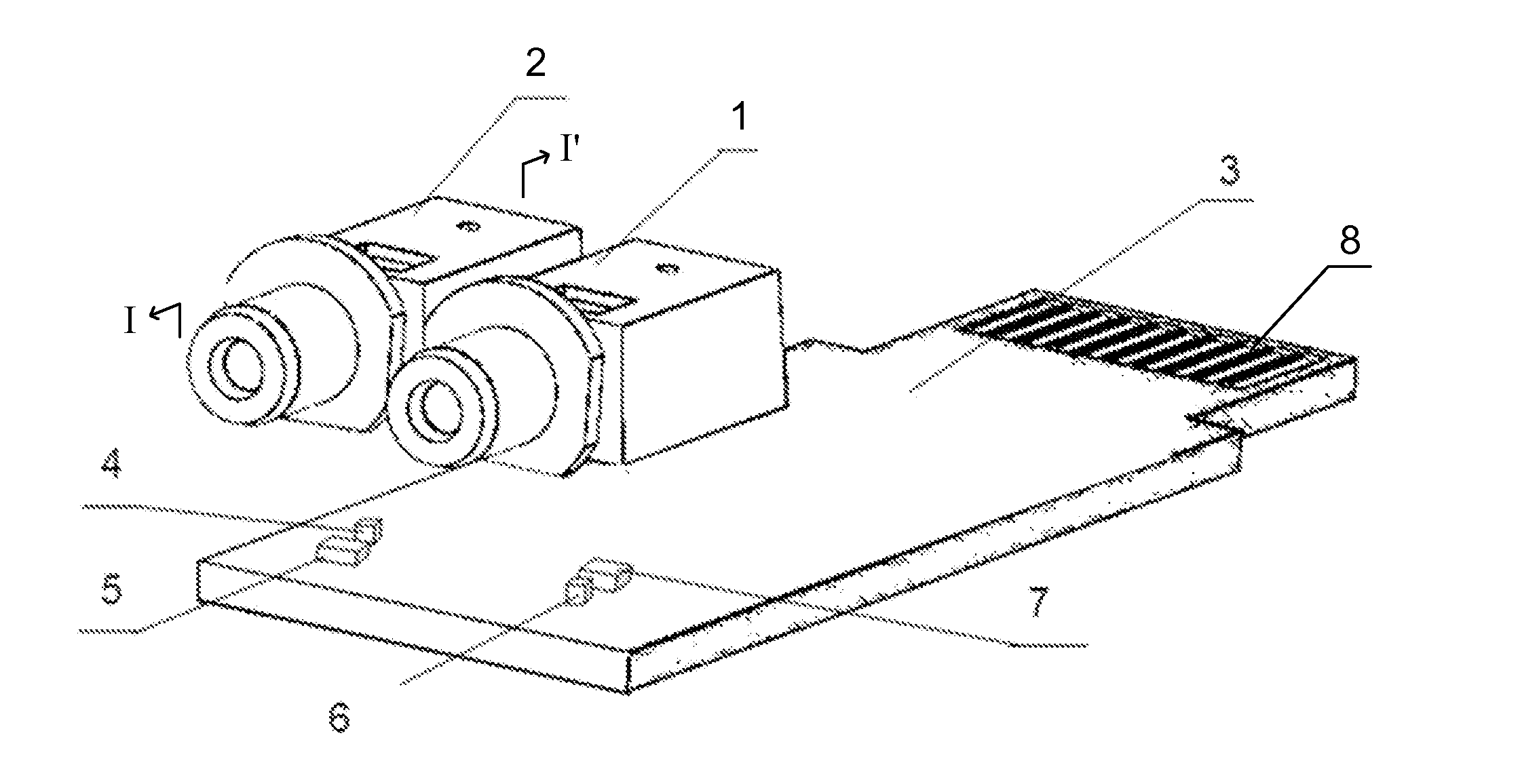
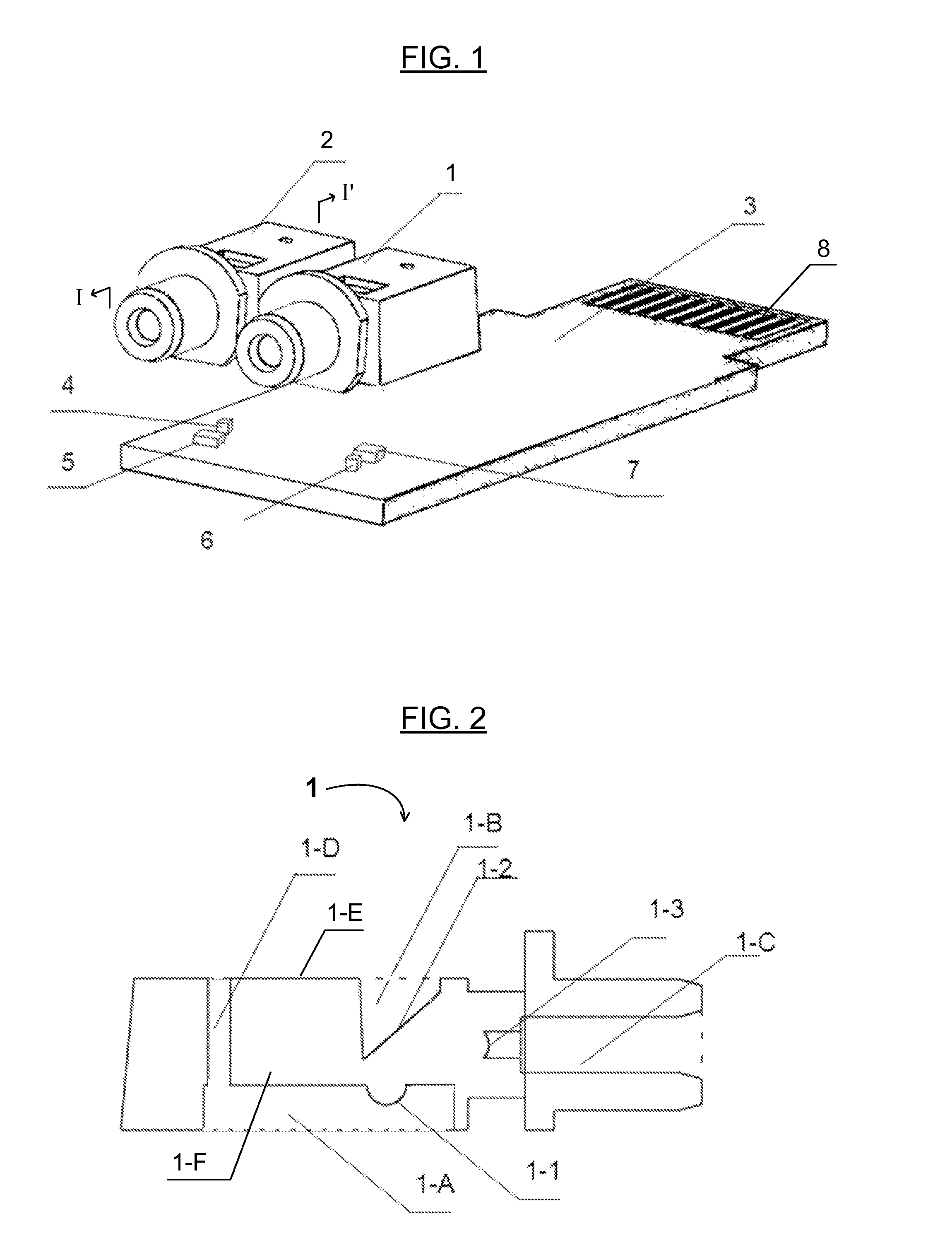
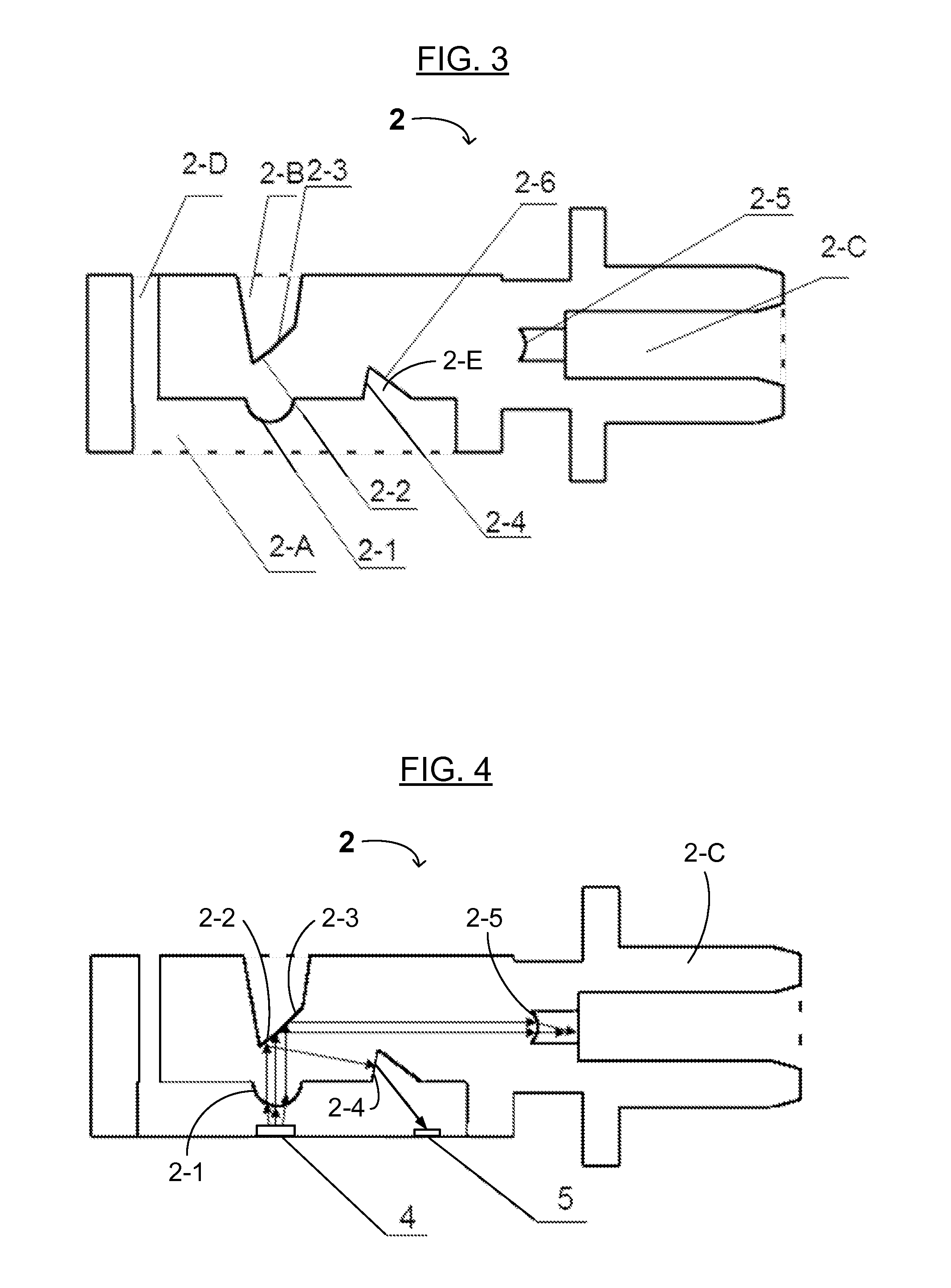
[0028]A method of transmitting an optical signal using the present integrated lens having multiple optical surfaces includes aligning or focusing the optical signal from an optical transmitter (which may be on a PCB) with the first lens onto the first optical surface, reflecting the optical signal from the first optical surface to the second lens on a face of the fiber adapter, and focusing the reflected optical signal onto a fiber in the fiber adapter. The method of transmitting the optical signal may further comprise reflecting a part of the focused optical signal from the second optical surface to the third optical surface, then further reflecting the reflected optical signal to a monitoring detector. Most of the focused optical signal is reflected by the second optical surface.
[0029]A method of receiving an optical signal using the present integrated lens having multiple optical surfaces includes aligning or focusing the optical signal from a fiber in the fiber adapter with the second lens onto the first optical surface, reflecting the optical signal from the first optical surface to the first lens, and focusing the reflected optical signal onto an optical receiver (which may be on the PCB) with the first lens.
[0030]The present device and methods enable not only the connection between optical fibers and optical transmitters and / or receivers, but also optical coupling of the optical signal from an optical transmitter to a fiber and from a fiber to an optical receiver. In addition, the transmitter integrated lens may reflect a small part of the optical signal from the transmitter to a monitoring photodiode for optical signal detection and / or power measurement. The present device and optical signal receiving method may achieve synchronous optical signal detection in an optical transmitter or receiver. The integrated lens includes multiple integrated lenses and optical surfaces instead of separate or discrete passive optical components, optimizes the light path and device structure, greatly reduces production cost, has a simple and / or unitary structure and high optical coupling efficiency, may have a small size and light weight, and is applicable to various optical signal coupling connections.

Problems solved by technology

Miniaturization brings more and more functional blocks and / or structures integrated into a limited device space, and accordingly, the connections and / or interface(s) between the optical module and the communication system become more complicated.
In this way, the production cost of optical modules goes down greatly, while the structure of the device generally becomes more compact.
However, the cost and complexity of conventional optical coupling and / or connecting devices is high.
Many conventional optical coupling and / or connecting devices employ a plurality of individual optical lenses to focus, change or conduct light paths of optical signals, and the installation and production of such individual lenses may be unacceptably complicated, costly and / or inefficient.

Method used


Image

  • Integrated lens with multiple optical structures and/or surfaces, optical module and transceiver including the same, and methods of making and using the same
  • Integrated lens with multiple optical structures and/or surfaces, optical module and transceiver including the same, and methods of making and using the same
  • Integrated lens with multiple optical structures and/or surfaces, optical module and transceiver including the same, and methods of making and using the same

Examples


Embodiment Construction

[0041]Reference will now be made in detail to various embodiments of the invention, examples of which are illustrated in the accompanying drawings. While the invention will be described in conjunction with the following embodiments, it will be understood that the descriptions are not intended to limit the invention to these embodiments. On the contrary, the invention is intended to cover alternatives, modifications and equivalents that may be included within the spirit and scope of the invention as defined by the appended claims. Furthermore, in the following detailed description of the present invention, numerous specific details are set forth in order to provide a thorough understanding of the present invention. However, it will be readily apparent to one skilled in the art that the present invention may be practiced without these specific details. In other instances, well-known methods, procedures, components, and circuits have not been described in detail so as not to unnecessar...


PUM

PropertyMeasurementUnit
angleaaaaaaaaaa
angleaaaaaaaaaa
angleaaaaaaaaaa

Abstract

An integrated lens with integrated functional optical surfaces for use in optical communication is disclosed. The integrated lens includes first and second cavities and a fiber adapter. The device also includes integrated first and second lenses. The first cavity houses one or more optical transmitting and/or receiving devices. The second cavity has a first optical surface and an optional second optical surface. The fiber adapter has the second lens. The integrated lens enables a small size, a light weight, high coupling and a high transmission efficiency, and can be produced by injection molding using a single mold. The integrated lens is applicable to optical signal coupling, fiber connections, optical modules, and optical or optoelectronic communication.

Description

RELATED APPLICATIONS[0001]This application is a continuation-in-part of U.S. patent application Ser. No. 14 / 426,326, filed Mar. 5, 2015 (Attorney Docket No. SP-340-L), pending, which is a national phase application of International Pat. Appl. No. PCT / CN2015 / 072957, filed Feb. 12, 2015, both of which are incorporated herein by reference in their entireties.FIELD OF THE INVENTION[0002]The present invention relates to the field of optical communication, especially to optical modules for multi-mode optical or optoelectronic communication.DISCUSSION OF THE BACKGROUND[0003]At present, optical communication is highly miniaturized and fast. As optical modules play an important role in facilitating the development and modernization of the optical communications industry, smaller and faster optical modes are continuously needed. Miniaturization brings more and more functional blocks and / or structures integrated into a limited device space, and accordingly, the connections and / or interface(s) ...

Claims


Application Information

Patent Timeline
Patent Type & Authority Applications(United States)
IPC IPC(8): G02B6/32H04B10/40G02B1/04G02B6/42G02B6/38H04B10/50H04B10/67
CPCG02B6/32H04B10/501H04B10/40H04B10/67G02B1/041G02B6/3865G02B6/3825G02B6/4292G02B6/4214G02B6/4286
Inventor TANG, XIAOHUIWANG, QIANGWU, KUIXU, YUANZHONG
Owner SOURCE PHOTONICS CHENGDU
Why Eureka
Try Eureka