Cooling system with integrated fill and drain pump

a technology of filling pump and cooling system, which is applied in the direction of liquid fuel engines, machines/engines, light and heating apparatus, etc., can solve the problems of continuing to pose cooling challenges at the module and system level, and the approach is becoming problematic, so as to facilitate selective filling of the cooling system and facilitate the circulation of coolan

Active Publication Date: 2016-08-18
IBM CORP
View PDF9 Cites 28 Cited by
  • Summary
  • Abstract
  • Description
  • Claims
  • Application Information

AI Technical Summary

Benefits of technology

[0003]The shortcomings of the prior art are addressed and additional advantages are provided through the provision, in one aspect, of a system which includes a cooling system for cooling one or more electronic components. The cooling system includes: a coolant circulation loop; at least one primary coolant pump coupled to facilitate circulating coolant through the coolant circulation loop; and a fill and drain

Problems solved by technology

This trend continues to pose cooling challenges at the module and system levels

Method used


Image

  • Cooling system with integrated fill and drain pump
  • Cooling system with integrated fill and drain pump
  • Cooling system with integrated fill and drain pump

Examples


Embodiment Construction

[0024]Reference is made below to the drawings, wherein the same or similar reference numbers used throughout different figures designate the same or similar components.

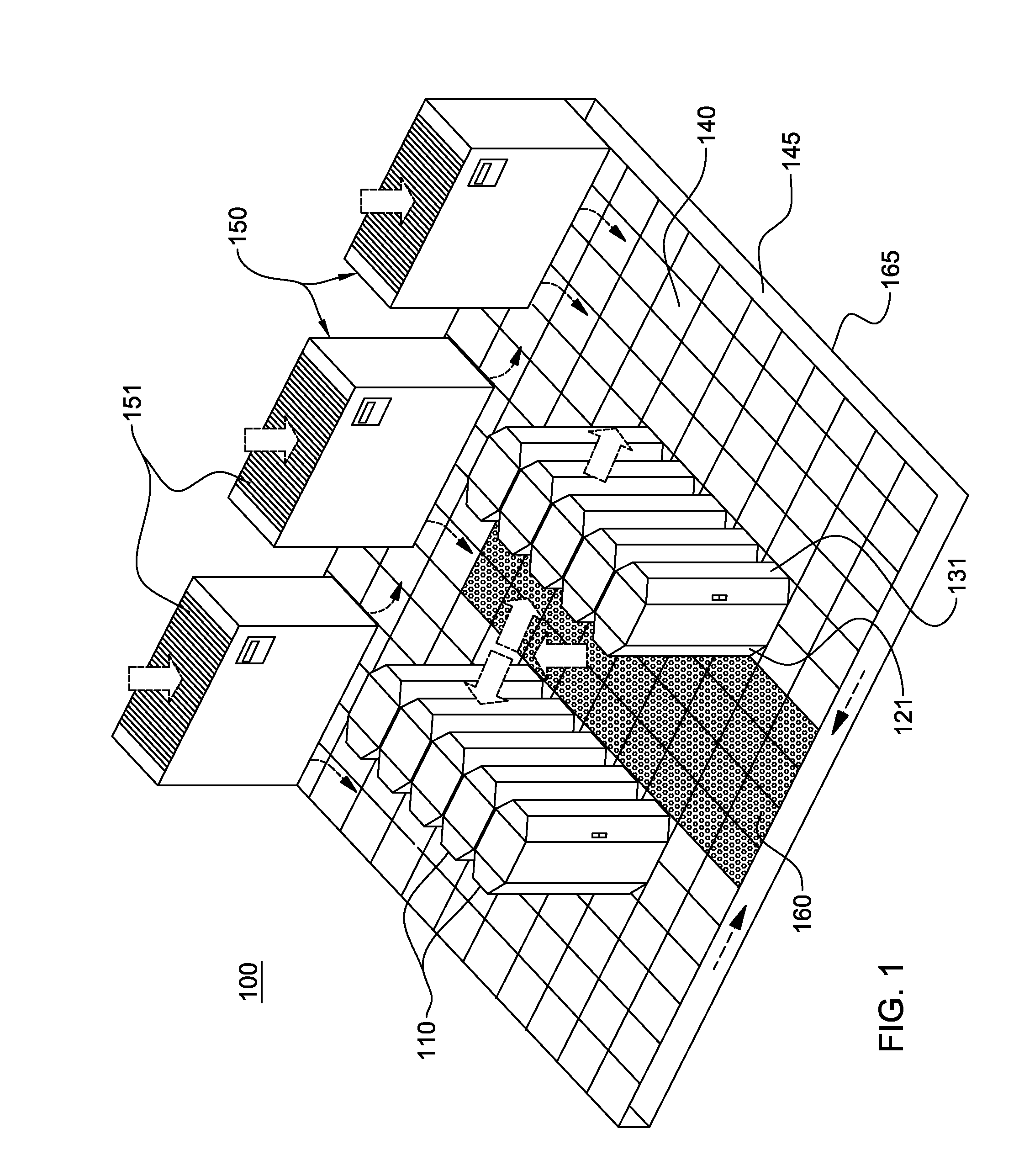
[0025]As shown in FIG. 1, in one implementation of a raised floor layout of an air-cooled data center 100, multiple electronics racks 110 are disposed in one or more rows. Note that “electronics rack”, “rack unit”, “rack”, “information technology (IT) infrastructure”, etc., may be used interchangeably herein, and unless otherwise specified, include any housing, frame, support, structure, compartment, etc., having one or more heat-generating components of a computer system, electronic system, IT system, etc. A computer installation such as depicted in FIG. 1 may house several hundred, or even several thousand microprocessors. In the arrangement of FIG. 1, chilled air enters the computer room via floor vents from a supply air plenum 145 defined between a raised floor 140 and a base or sub-floor 165 of the room. Cooled a...


PUM


Abstract

A cooling system is provided which includes, for instance, a coolant circulation loop, one or more primary coolant pumps, and a fill and drain pump. The primary coolant pump(s) is coupled to facilitate circulating coolant through the coolant circulation loop, and the fill and drain pump facilitates selective filling of the cooling system with the coolant, or draining of the coolant from the cooling system. The fill and drain pump is integrated with the cooling system as a backup coolant pump to the primary coolant pump(s), and circulates the coolant through the coolant circulation loop responsive to an error in the primary coolant pump(s). The primary coolant pump(s) and fill and drain pumps may be different types of pumps, and the cooling system further includes a control system for automatically activating the fill and drain pump upon detection of an error in the primary coolant pump(s).

Description

BACKGROUND[0001]The power dissipation of integrated circuit chips, and the modules containing the chips, continues to increase in order to achieve increases in processor performance. This trend continues to pose cooling challenges at the module and system levels.[0002]In many large server applications, processors along with their associated electronics (e.g., memory, disk drives, power supplies, etc.) are packaged in removable drawer configurations stacked within an electronics rack or frame comprising information technology (IT) equipment. In other cases, the electronics may be in fixed locations within the rack or frame. Conventionally, the components have been cooled by air moving in substantially parallel airflow paths, usually front-to-back, impelled by one or more air moving assemblies (e.g., axial or centrifugal fans). In some cases it has been possible to handle increased power dissipation within a single drawer or system by providing greater airflow, for example, through th...

Claims


Application Information

Patent Timeline
IPC IPC(8): H05K7/20
CPCH05K7/20254H05K7/20272F04D9/00F04D13/12F04D25/16F04D29/586F28F2265/06H05K7/20781
Inventor EDWARDS, DAVID L.GOTH, GARY F.KEARNEY, DANIEL J.KELLY, PETER W.KRUG, JR., FRANCIS R.MULLADY, ROBERT K.PORTER, DONALD W.VANDEVENTER, ALLAN C.ZOODSMA, RANDY J.
Owner IBM CORP
Why Eureka
Try Eureka