Optical system for 3D printing and control method thereof

a technology of optical system and 3d printing, applied in the field of 3d printing, can solve the problems of slow printing mode, low efficiency, slow printing speed, etc., and achieve the effect of improving the printing efficiency of the 3d printing system, and high quality of 3d printing

Inactive Publication Date: 2016-08-25
GUANGZHOU INST OF ADVANCED TECH CHINESE ACAD OF SCI
View PDF1 Cites 41 Cited by
  • Summary
  • Abstract
  • Description
  • Claims
  • Application Information

AI Technical Summary

Benefits of technology

[0028]The present invention has the following beneficial effects: the present invention provides an optical system for 3D printing, including a laser device, a beam expanding system, a beam splitter, a spatial light modulator and a focusing system, wherein the spatial light modulator is connected with a computer for generating a target modulation pattern and configured to generate a modulation pattern after receiving the target modulation pattern generated by the computer. In the optical system, the target modulation pattern is generated by a computer and then sent to the spatial light modulator to generate a modulation pattern, so that the light beam is focused onto a target plane for 3D printing after modulated. Compared with the point-by-point focusing in the prior art, the optical system performs optical modulation and focusing demodulation in unit of modulation pattern, may realize line-by-line printing, segment-by-segment printing and even whole-plane printing, greatly improves the printing efficiency of the 3D printing system, and meanwhile ensures the high quality of 3D printing.
[0029]The present invention has the following other beneficial effects: the present invention provides a control method of an optical system for 3D printing, including: after acquiring a planar pattern of each plane of a printing mode...

Problems solved by technology

However, the industrial popularization and application of the 3D printing technology still have many problems, a key problem of which is slow prin...

Method used


Image

  • Optical system for 3D printing and control method thereof
  • Optical system for 3D printing and control method thereof
  • Optical system for 3D printing and control method thereof

Examples


embodiment 1

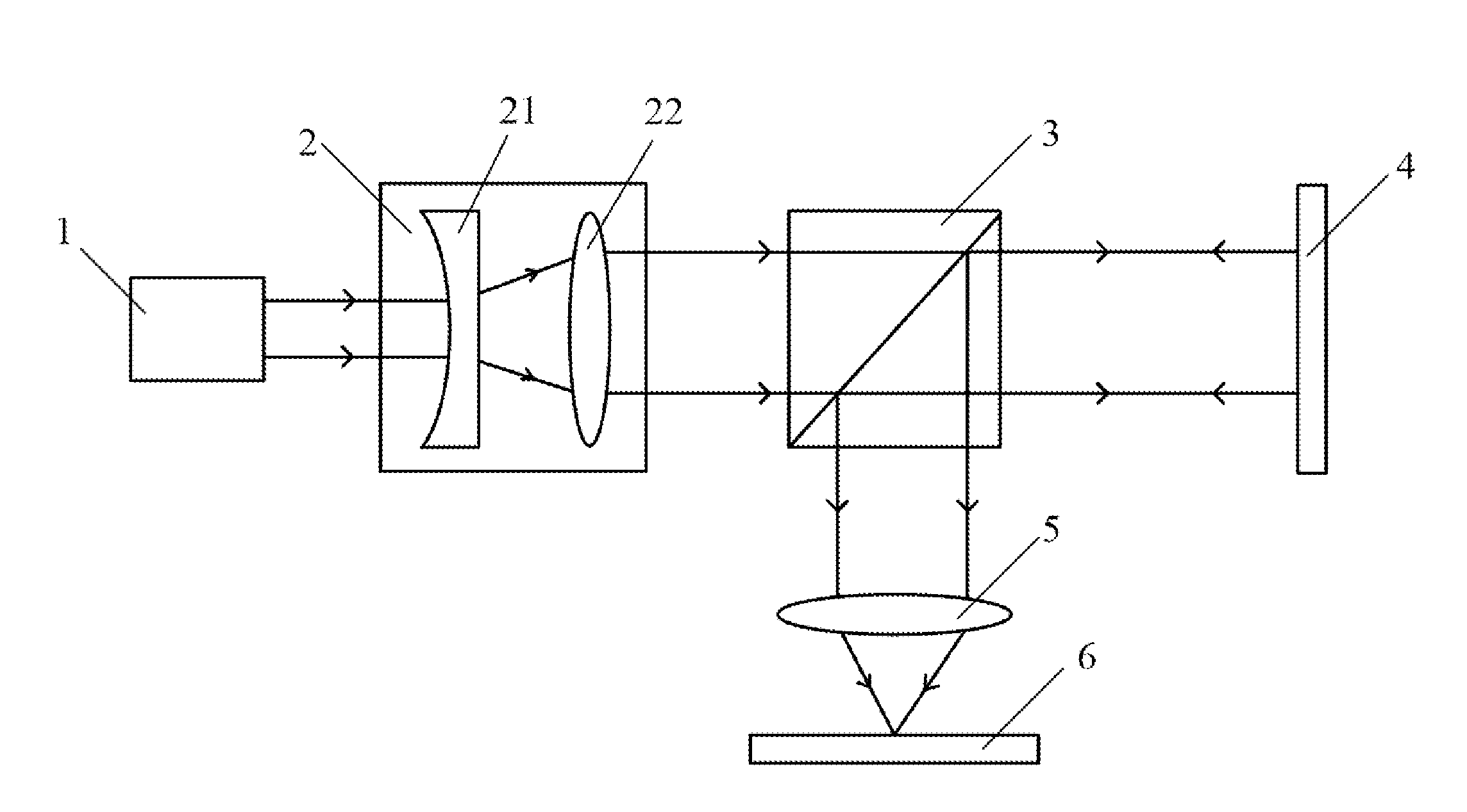
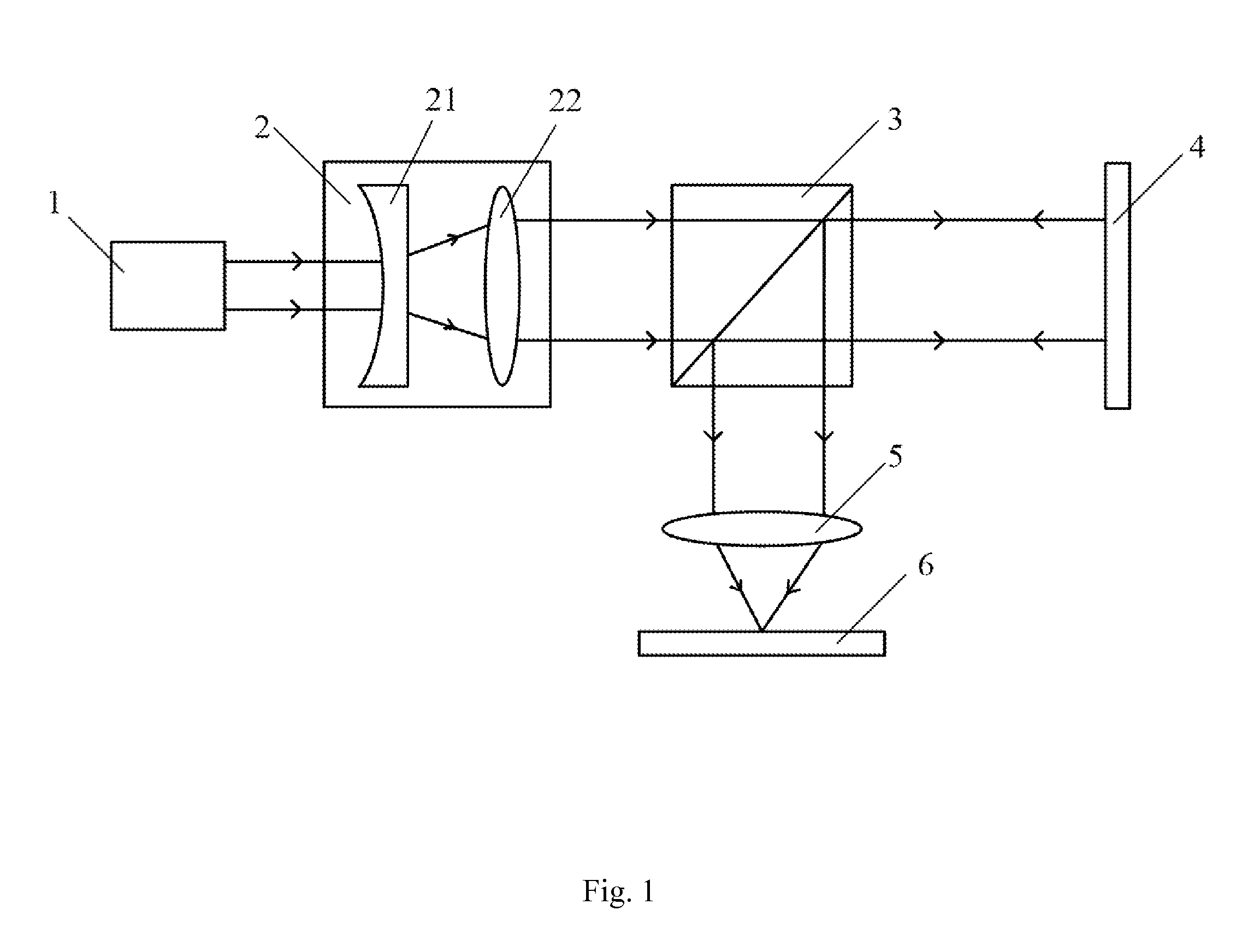
[0065]Referring to FIG. 1, an optical system for 3D printing is provided, including a laser device 1, a beam expanding system 2, a beam splitter 3, a spatial light modulator 4 and a focusing system 5. The spatial light modulator 4 is connected with a computer for generating a target modulation pattern and configured to generate a modulation pattern after receiving the target modulation pattern generated by the computer, and configured to modulate a light beam that irradiates on the spatial light modulator 4. A light beam emitted by the laser device 1 is expanded into a parallel light beam having a large diameter by the beam expanding system and then irradiates on the beam splitter 3. A part of the expanded light beam reaches the spatial light modulator 4 for modulation after passing through the beam splitter 3, then the modulated light beam is reflected to the beam splitter 3, and a part of the modulated light beam is focused by the focusing system 5 and then irradiates on a target ...

embodiment 2

[0069]Referring to FIG. 1, an optical system for 3D printing is provided, including a laser device 1, a beam expanding system 2, a beam splitter 3, a spatial light modulator 4 and a focusing system 5. The spatial light modulator 4 is connected with a computer for generating a target modulation pattern, and configured to generate a modulation pattern after receiving the target modulation pattern generated by the computer, and configured to modulate a light beam that irradiates on the spatial light modulator 4. A light beam emitted by the laser device 1 is expanded into a parallel light beam having a large diameter by the beam expanding system and then irradiates on the beam splitter 3. A part of the expanded light beam reaches the spatial light modulator 4 for modulation after passing through the beam splitter 3, then the modulated light beam is reflected to the beam splitter 3, and a part of the modulated light beam is focused by the focusing system 5 and then irradiates on a target...

embodiment 3

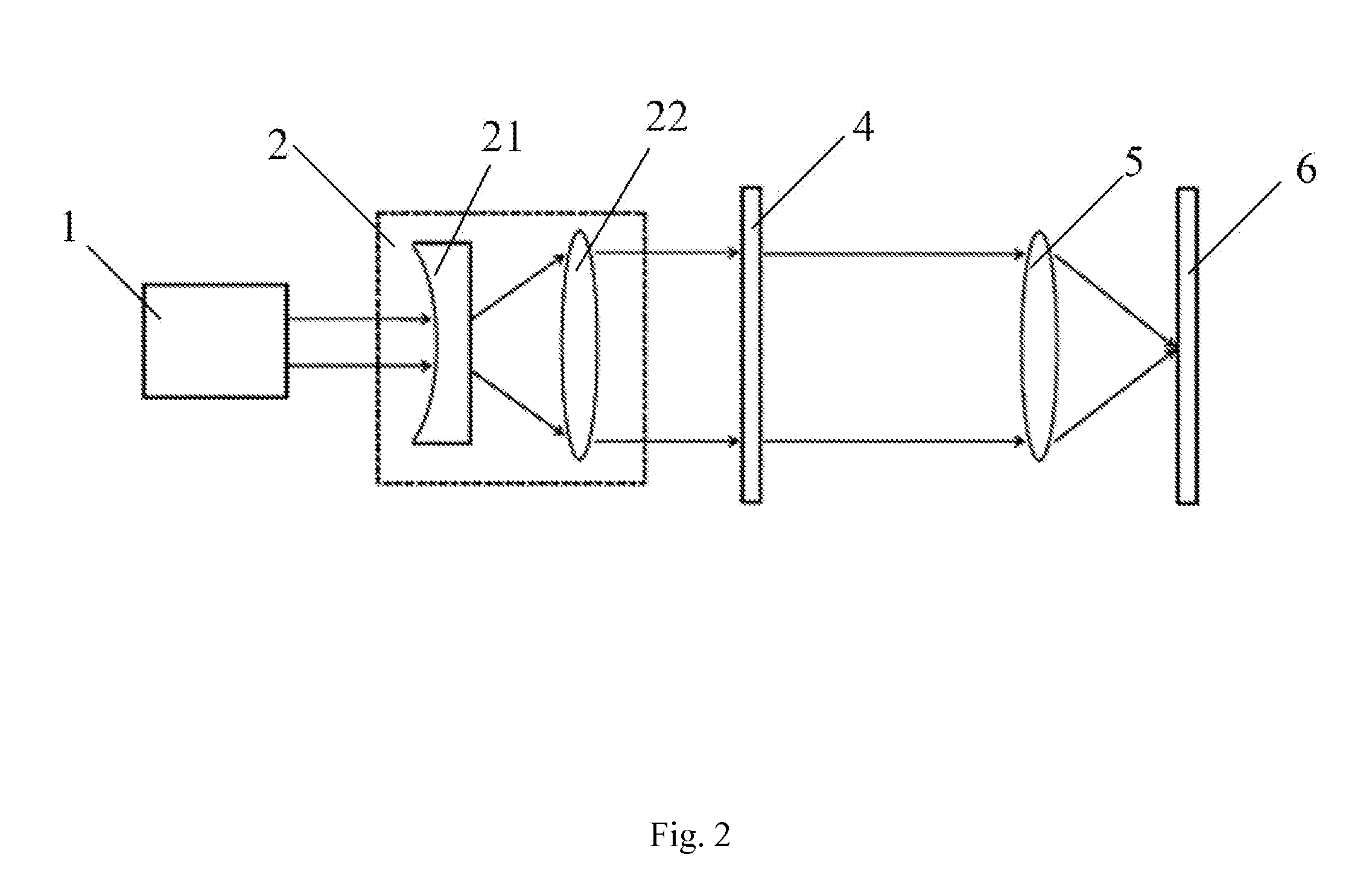
[0073]Referring to FIG. 2, an optical system for 3D printing is provided, including a laser device 1, a beam expanding system 2, a spatial light modulator 4 and a focusing system 5. The spatial light modulator 4 is connected with a computer for generating a target modulation pattern and configured to generate a modulation pattern after receiving the target modulation pattern generated by the computer, and configured to modulate a light beam that irradiates on the spatial light modulator 4. A light beam emitted by the laser device 1 is expanded into a parallel light beam having a large diameter by the beam expanding system and then irradiates on the spatial light modulator 4 for modulation, and then the modulated light beam is focused by the focusing system 5 and then irradiates on a target plane 6 for 3D printing.

[0074]In this embodiment, the beam expanding system 2 includes a negative lens 21 and a positive lens 22, with the axis of the negative lens 21 and the axis of the positive...


PUM

PropertyMeasurementUnit
Widthaaaaaaaaaa

Abstract

The present invention discloses an optical system for 3D printing and a control method thereof. The system comprises a laser device, a beam expanding system, a beam splitter, a spatial light modulator and a focusing system. The spatial light modulator is connected with a computer and configured to generate a modulation pattern after receiving the target modulation pattern generated by the computer. A light beam emitted by the laser device is expanded into a parallel light beam by the beam expanding system and then irradiates on the beam splitter. A part of the expanded light beam reaches the spatial light modulator for modulation after passing through the beam splitter, then the modulated light beam is reflected to the beam splitter, and a part of the modulated light beam is focused by the focusing system and then irradiates on a target plane for 3D printing.

Description

FIELD OF THE INVENTION[0001]The present invention relates to the field of 3D printing, in particular to an optical system for 3D printing and a control method thereof.BACKGROUND OF THE INVENTION[0002]Due to its ability to directly actualize a digital model, the 3D printing technology may change conventional designs and manufacturing methods. At present, the 3D printing has been applied in aerospace, medical treatment, automobiles and other many fields. However, the industrial popularization and application of the 3D printing technology still have many problems, a key problem of which is slow printing speed. All existing 3D printing devices, including Selective Laser Sintering (SLS), Selective Laser Melting (SLM) or the like, depend on point-by-point and layer-by-layer printing using a single beam or multiple beams of laser, and the movement of the focus of a light beam is controlled by a reflector and a lens combination both controlled by a micro electromechanical system so as to re...

Claims


Application Information

Patent Timeline
IPC IPC(8): B23K26/342B23K26/06B28B17/00B23K26/067B29C67/00B28B1/00
CPCB29C67/00B33Y10/00B29C67/0088B29C67/0077B28B17/0063B28B1/001B23K26/067B23K26/0648B22F2003/1057B22F3/1055B23K26/342B33Y50/02B29K2105/251B33Y30/00B29C64/153B29C64/393Y02P10/25B22F10/28B22F10/80B22F12/44
Inventor ZHENG, ZHUEICHSTAEDT, OLAFREN, YUNPENGDU, RUXU
Owner GUANGZHOU INST OF ADVANCED TECH CHINESE ACAD OF SCI
Why Eureka
Try Eureka