Method and device for wire cutting of a material

Inactive Publication Date: 2016-08-25
COMMISSARIAT A LENERGIE ATOMIQUE ET AUX ENERGIES ALTERNATIVES
View PDF10 Cites 1 Cited by
  • Summary
  • Abstract
  • Description
  • Claims
  • Application Information

AI Technical Summary

Benefits of technology

[0055]An object of the invention is therefore to design a method (with a wire with bound abrasive or with a slurry) for wire cutting a material which a

Problems solved by technology

The main obstacle to the development of the wire with a bound abrasive is its high cost—about a hundred times greater than that of the smooth wire used in the cutting with the slurry.
Indeed, a wire loses its capacity of removing material gradually during the cuttings.
This may lead to a quasi-zero abrasion speed, if there is no breaking of the wire beforehand.
The replacement of the worn wire is therefore never optimized relatively to its actual wearing condition.
This adjustment is also carried out empirically and is very difficult to optimize systematically.
Moreover, the breakage remains substantially unpredictable.
The breakage may be ascribed to weakness of the wire, to the heterogeneities of the material to be cut or further to poor selection of the cutting parameters.
Considering these inhomogeneities, it is presently difficult, or even impossible to define cutting parameters locally adapted to the cut-out material giving the possibility of reducing the wear of the wire and also its risks of breaking.
Other machining methods are subject to problems of wearing of the tool, notably grinders.
It was observed that the wear of the grinders has the consequence of increasing the cutting forces [1].
However, this general relationship cannot be utilized alone for reduci

Method used


Image

  • Method and device for wire cutting of a material
  • Method and device for wire cutting of a material
  • Method and device for wire cutting of a material

Examples


Example

Cutting Device

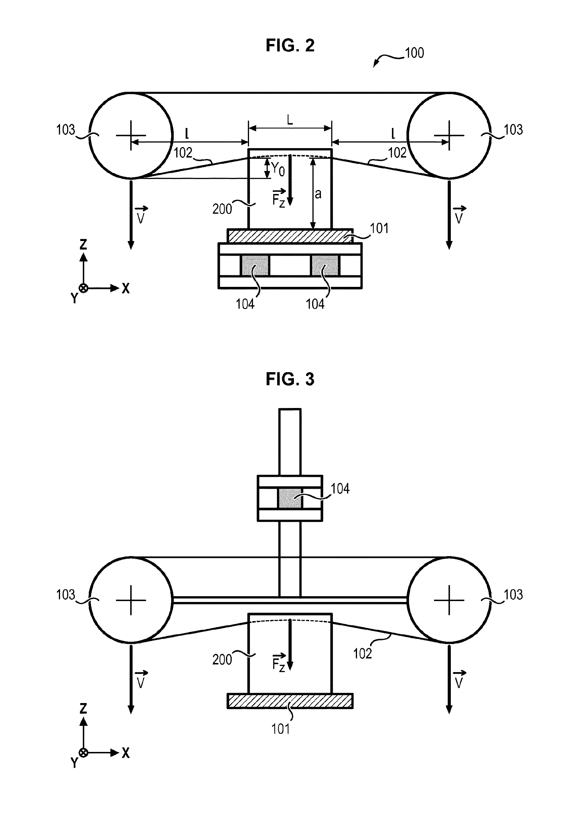
[0115]FIG. 2 schematically illustrates an embodiment of a wire cutting device.

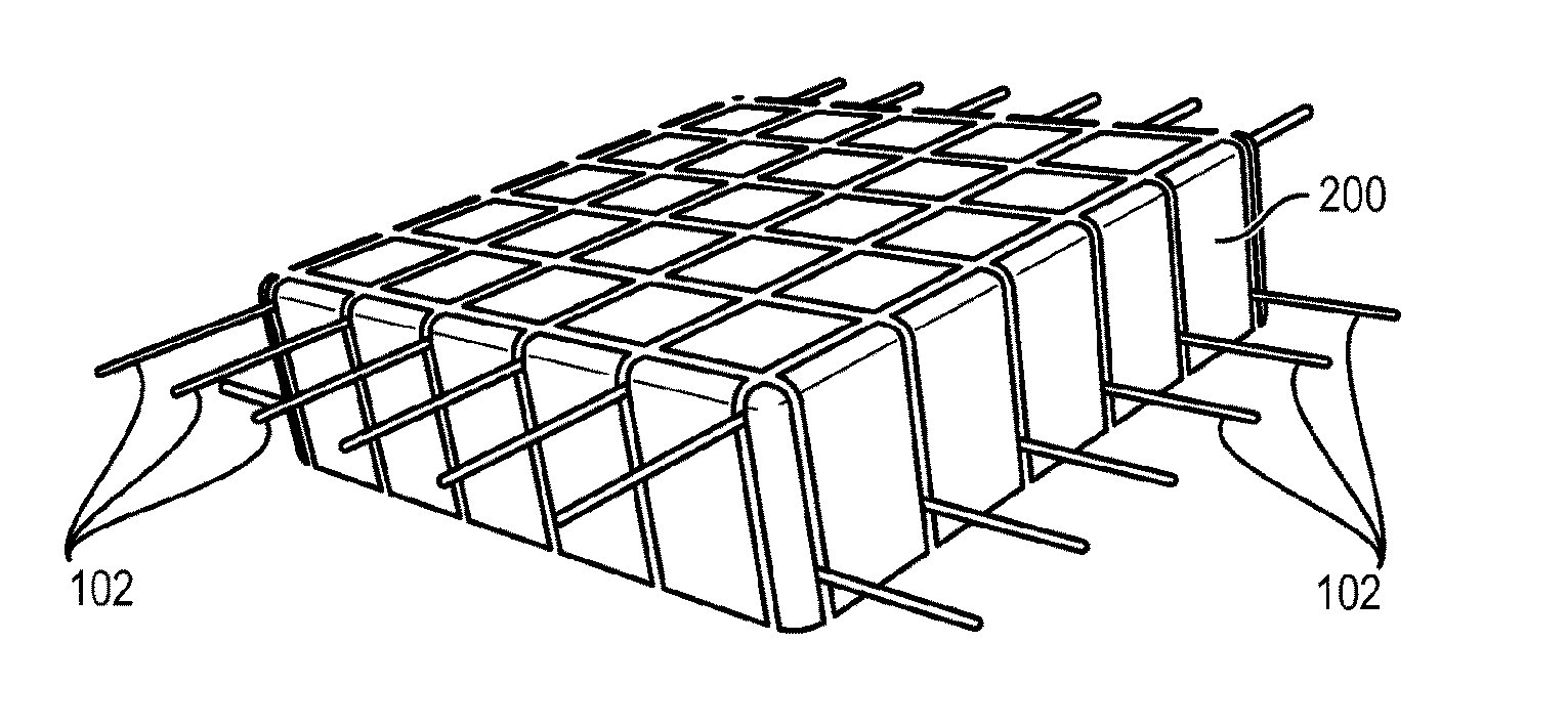
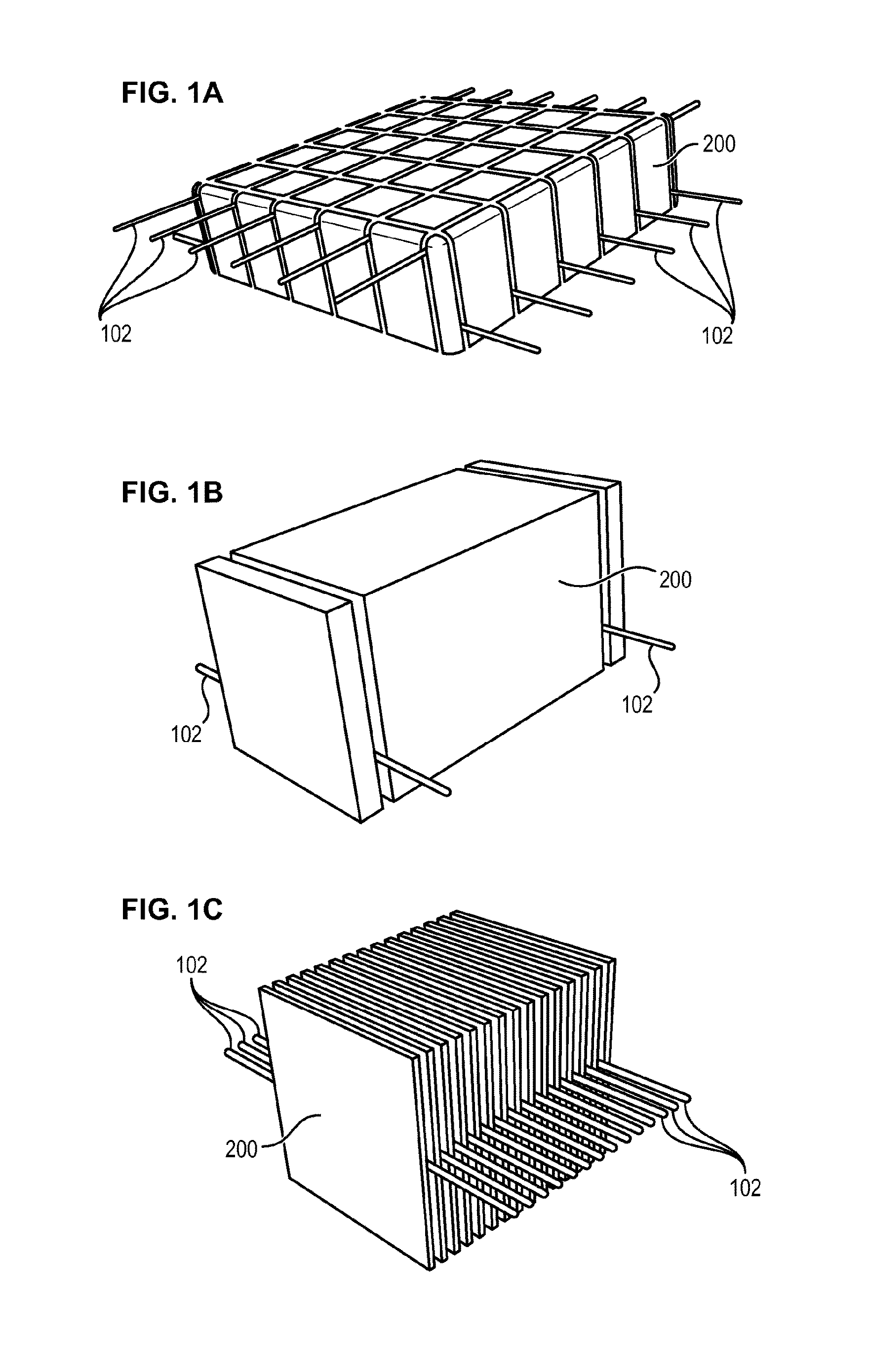
[0116]Said device 100 comprises a support 101 for positioning and, if required, maintaining the material 200 to be cut, which is here represented as a parallelepipedal block.

[0117]However it is obvious that the material to be cut may have another shape without however departing from the scope of the invention.

[0118]Without the invention being limited to these materials, the material 200 to be cut is advantageously silicon, in particular silicon for a photovoltaic application, quartz or sapphire.

[0119]The material 200 is cut out by means of at least one cutting wire 102 which is driven so as to run in a direction parallel to the cutting line.

[0120]In the example illustrated here, the wire 102 forms a loop surrounding two pulleys 103 belonging to the wire guiding system which are laid out so as to guide the wire during the cutting of the material.

[0121]This embodiment is however not limiting an...


PUM


Abstract

The invention relates to a method for wire cutting of a material, wherein a cutting wire is advanced into the material by causing said wire to scroll in such a way as to progressively cut the material, the method being characterised in that it comprises: the measurement of a force applied by the wire on the material as a function of time, the measurement of the advancement of the wire in the material as a function of time, the determination, as a function of said force and said advancement of the wire, of a variable characterising the state of the wire cutting and, servo control of at least one cutting parameter through changes in said variable so as to reduce the rate of wear of the wire and/or to reduce the risk of breaking of the wire. The invention also relates to a device for wire cutting allowing implementation of said method.

Description

FIELD OF THE INVENTION[0001]The present invention relates to a method and device for wire cutting a preferably fragile material.BACKGROUND OF THE INVENTION[0002]Wire saws are used in many fields, from among which may be mentioned the cutting of semi-conducting materials (such as silicon) for forming substrates, the cutting of wood and the cutting of stone.[0003]Wire saws consist of one or several free wires or in the form of a loop set into motion by a system of pulleys.[0004]Cutting is allowed by abrasion phenomena between the wire and the material to be cut, optionally assisted by the action of a third body.[0005]This method is further generally lubricated with a fluid such as water, polyethylene-glycol (PEG), a gel, etc.[0006]Without any limiting intention, below the focus of interest is more specifically on the shaping of silicon for photovoltaic applications.[0007]Wire saws are actually used in all the cutting steps applied for passing from an ingot to the substrates (or “wafer...

Claims


Application Information

Patent Timeline
IPC IPC(8): B28D5/00G05B19/418B28D5/04
CPCB28D5/0064B28D5/045G05B2219/50331G05B2219/45031G05B19/418
Inventor SILLARD, LEOGARANDET, JEAN-PAULPENOT, JEAN-DANIEL
Owner COMMISSARIAT A LENERGIE ATOMIQUE ET AUX ENERGIES ALTERNATIVES
Why Eureka
Try Eureka