
Sludge drying beds

a technology of sludge drying and sludge, which is applied in the direction of energy-based wastewater treatment, sedimentation separation, and separation processes, can solve the problems of increasing sludge generation, increasing sludge generation, and increasing the cost of sludge transport/hauling, and the cost and economics of current sludge transport/hauling are also significan

Inactive Publication Date: 2016-08-25
MOONEY JOHN
View PDF7 Cites 0 Cited by
  • Summary
  • Abstract
  • Description
  • Claims
  • Application Information

AI Technical Summary

Benefits of technology

The patent text describes a system that reduces the cost of wastewater treatment by using sludge drying beds. These beds use heat and gravity to dewater sludge, which results in reduced transport and disposal costs. The system also improves treatment efficiency and reduces the amount of sludge generated. Overall, this system offers both economic and environmental benefits.

Problems solved by technology

Elevated levels of colour and turbidity may require large chemical addition during treatment, increasing sludge generation.
The costs of handling the enormous quantities of sludge can account for a large percentage of the overall operating costs of water treatment works and are likely to increase due to increasingly stringent regulations.
The cost and economics of current sludge transport / haulage are also significant.
In wastewater treatment plants, hydrolyzing metal salts and organic polymers added to coagulate suspended and dissolved contaminants to facilitate wastewater purification represents a significant part of the overall current treatment process cost and the coagulants form an integral part of the sludge produced thereby restricting its beneficial reuse value.

Method used


Image

  • Sludge drying beds
  • Sludge drying beds
  • Sludge drying beds

Examples


Embodiment Construction

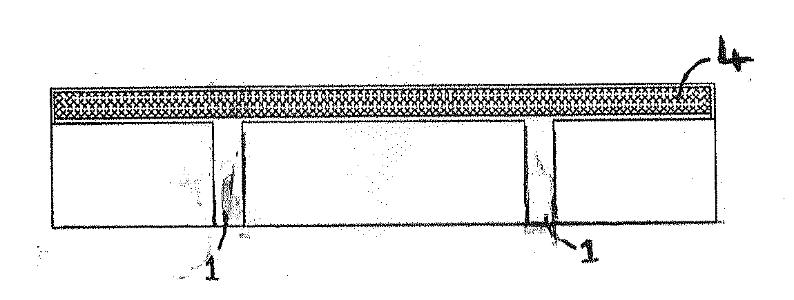
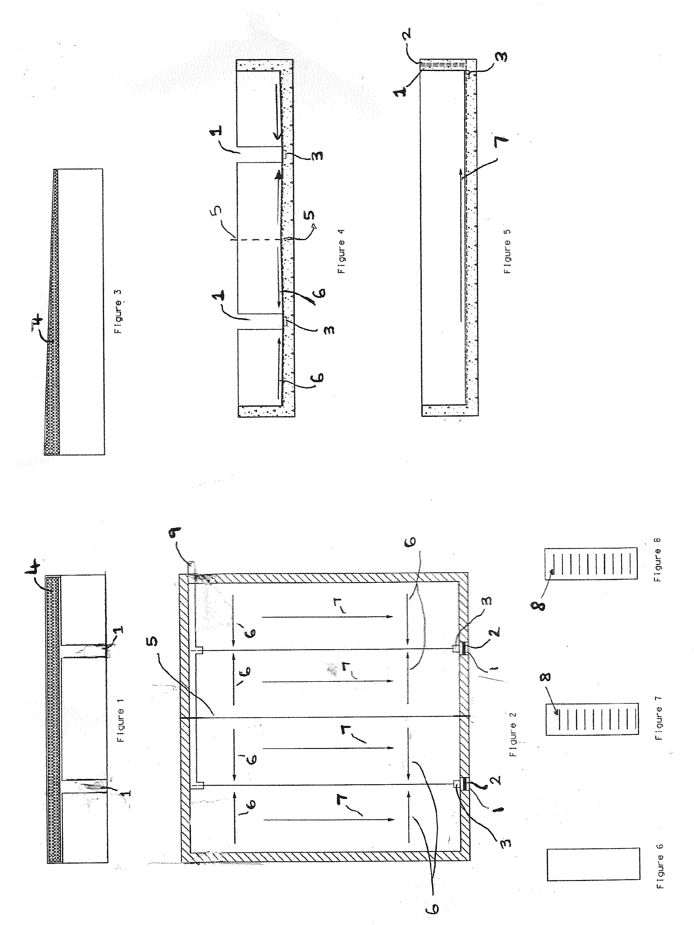
[0032]The design of the sludge drying bed provides for ease of operation and is determined by the treatment plant size. The sludge drying bed capacity is determined by such factors as: volume of sludge added, percent solids, and character; the temperature of the beds; the degree of solids reduction required; method of sludge disposal and the size of the plant. For operational purposes, the depth of the sludge placed on the drying bed may increase or decrease based on the percent solids content. Provision must be made to maintain sufficient continuity of service so that sludge may be dewatered without accumulation beyond the storage capacity of the beds.

[0033]The sludge drying beds are modular in design and may be scaled up by positioning the preferred embodiment of the sludge drying beds adjacent to each other, which may optionally be separated with or without a dividing wall, to cater for increased sludge volumes from domestic and commercial sewage and wastewater during the design ...


PUM

PropertyMeasurementUnit
Lengthaaaaaaaaaa
Lengthaaaaaaaaaa
Lengthaaaaaaaaaa

Abstract

A sludge drying bed for effective separation or decanting of water from sludge and the storage of treated sludge comprising of a sloping floor (6,7) to drain the water towards the sluice door (2) located in the front wall, two side-walls and a valve controlled filler inlet pipe (9) at the back wall where the sludge enters the bed. The sludge drying bed is covered by an openable pitched roof utilising a breathable, waterproof, black membrane as roof material for ventilation, heat absorption and surface water runoff. The sluice door (2) contains alternating plates to facilitate the filling of the sludge drying beds and the decanting of the water at multiple levels within the sludge, with a sump (3) located at the front wall to facilitate the efficient removal of the dried sludge from the beds. A telescopic handle, sludge drying bed cleaning tool is provided to facilitate the cleaning and maintenance of the sludge drying bed. The sludge drying beds are modular in design.

Description

[0001]The present invention relates to a process and apparatus for decanting water from sludge.[0002]Domestic, commercial and industrial wastewater and sewage is transported through a collection system to a wastewater treatment plant. Wastewater treatment is a process of sanitising wastewater and household sewage by removing contaminants to produce an environmentally safe, treated effluent and solid waste (known as treated sludge), which can be safely disposed of or reused as fertiliser. A great deal of wastewater effluent is discharged into rivers and seas with a Licencing regime in place to regulate the amount and quality of effluent that may be so discharged.[0003]The water is called influent before it enters one treatment step, and effluent when it emerges from that treatment step. The preliminary and primary treatment stages remove screenable (leaves, rags), floatable (oils and grease), and settleable (grit, food waste) materials from the influent wastewater. Secondary treatmen...

Claims


Application Information

Patent Timeline
IPC IPC(8): C02F11/16
CPCY02W10/37C02F11/16B01D21/2444
Inventor MOONEY, JOHN
Owner MOONEY JOHN
Learn More