
Magnetic field detection sensor

a detection sensor and magnetic field technology, applied in the field of magnetic field detection sensors, can solve the problems of increasing current consumption, affecting the detection accuracy of magnetic fields, and inability to make highly sensitive measurements, so as to improve detection accuracy, reduce current consumption, and increase the detection range

Active Publication Date: 2016-08-25
YAZAKI CORP
View PDF2 Cites 7 Cited by
  • Summary
  • Abstract
  • Description
  • Claims
  • Application Information

AI Technical Summary

Benefits of technology

The present invention aims to improve the magnetic field detection sensor by reducing current consumption, increasing detection precision, and expanding the detection range.

Problems solved by technology

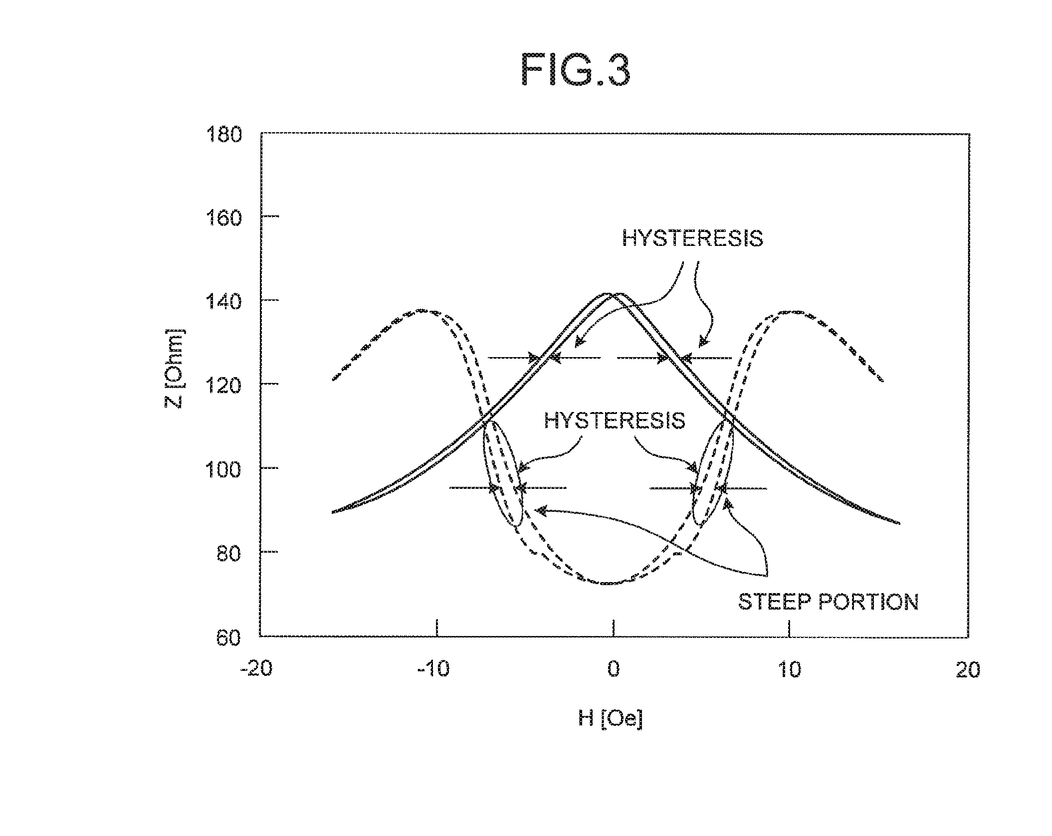
The magnetic field detection sensors disclosed in Japanese Patent Application Laid-open No. 9-127218 and Japanese Patent Application Laid-open No. 2000-180521 are, however, incapable of making highly sensitive measurement unless applied is an AC bias at a level at which the inclination of the impedance change becomes steep (up to ±400 A / m in FIG. 5 disclosed in Japanese Patent Application Laid-open No. 2000-180521), because the impedance that is dependent on the magnetic field of the MI element changes in an M-shape.
Therefore, the current consumption is increased.
Similarly, an approach for applying a DC bias at a level at which the inclination of the impedance change becomes steep requires an increased amount of current consumption.
Furthermore, because a hysteresis is increased in the M-shaped characteristics, the detection precision is deteriorated by the amount of the hysteresis.
Moreover, because the magnetic field can only be measured highly sensitively within the range where a steep inclination is ensured, only a limited detection range has been available.

Method used


Image

  • Magnetic field detection sensor
  • Magnetic field detection sensor
  • Magnetic field detection sensor

Examples


Embodiment Construction

[0024]An exemplary embodiment of the present invention will now be explained with reference to some drawings. The scope of the present invention is, however, not limited to the embodiment.

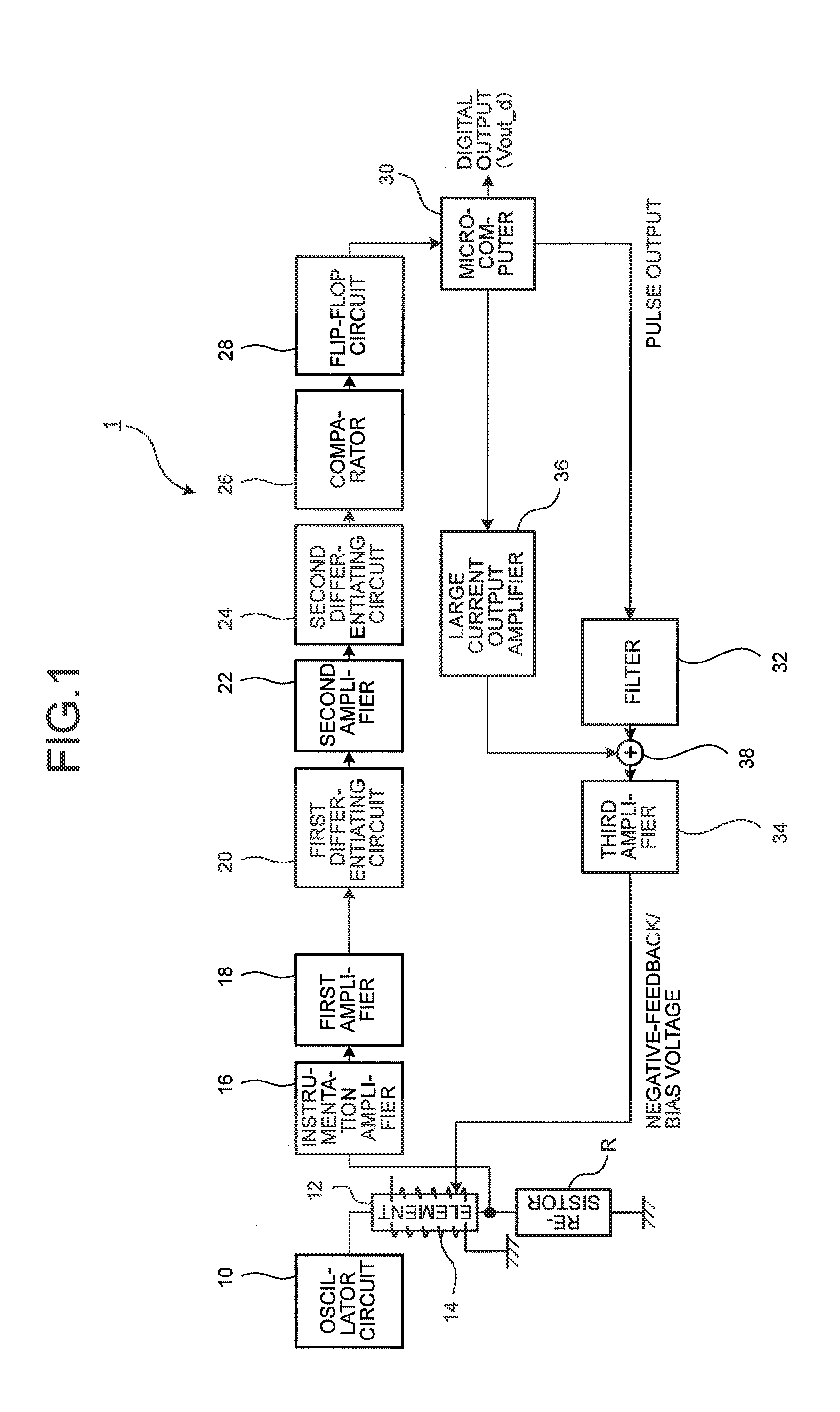
[0025]FIG. 1 is a circuit diagram schematically illustrating a magnetic field detection sensor according to an embodiment. This magnetic field detection sensor 1 illustrated in FIG. 1, which is provided as a magnetism detector, is configured to detect an external magnetic field (the direction, the azimuth, and the strength of the magnetism) based on an output of a magneto-impedance element 12 to which an AC current is applied, and is used as an element in a current sensor, an azimuth sensor, a torque sensor, or a rotation angle sensor, for example. Such a magnetic field detection sensor 1 serving as a magnetism detector includes an oscillator circuit 10, the magneto-impedance element 12, a resistor R, and a negative-feedback bias coil (bias coil) 14.

[0026]The oscillator circuit 10 is a source of an...


PUM


Abstract

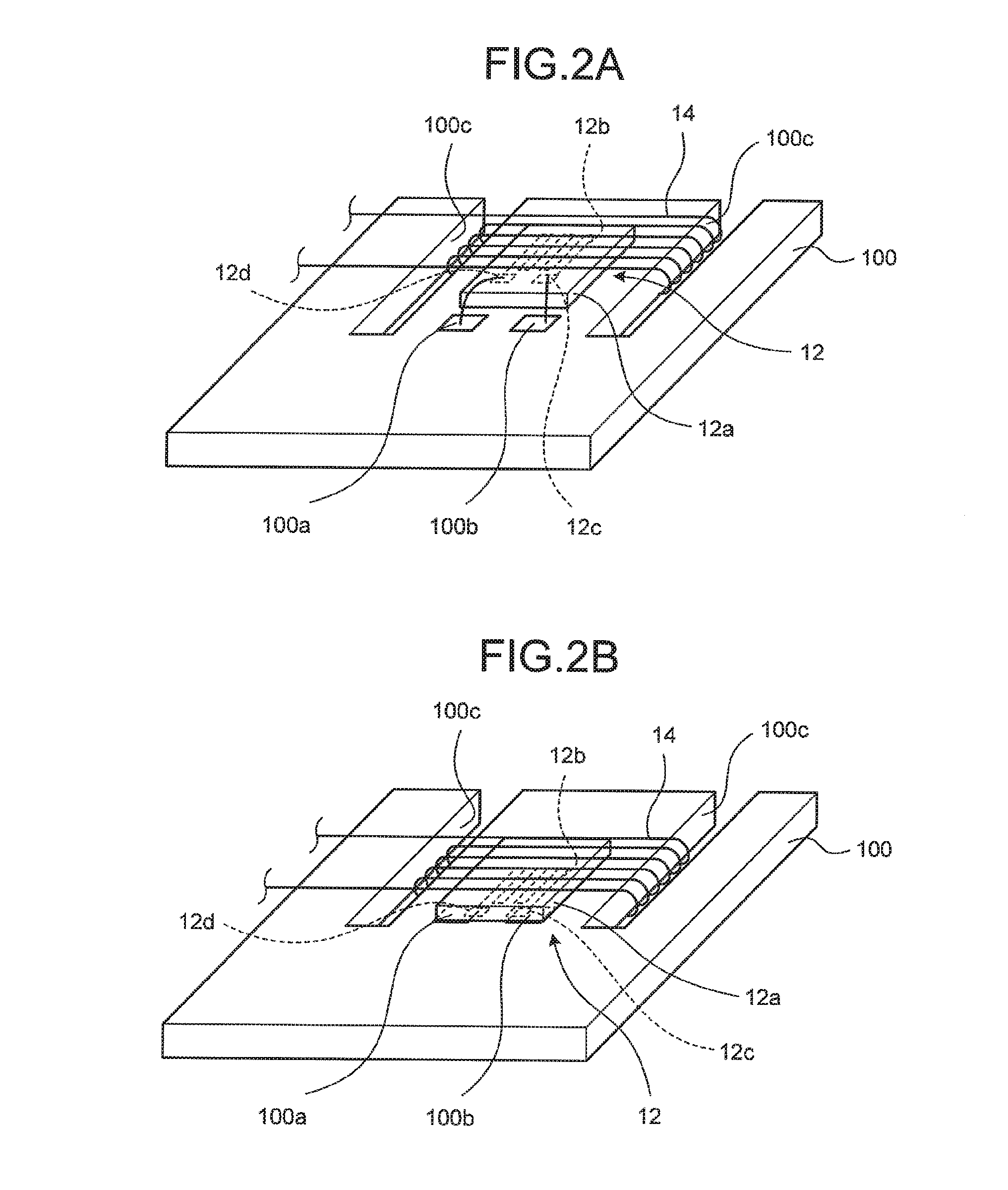
A magnetic field detection sensor includes a magneto-impedance element configured to make use of the magneto-impedance effect, and a negative-feedback bias coil configured to apply a bias magnetic field to the magneto-impedance element. The magnetic field detection sensor is configured to detect an external magnetic field based on an output obtained by applying an alternating-current to the magneto-impedance element. The magneto-impedance element includes a non-magnetic substrate, and a magnetic thin-film that is provided on a surface of the non-magnetic substrate. The magnetic field detecting direction matches the longitudinal direction of the magneto-impedance element, and the magnetic thin-film is configured to have a magnetic anisotropy such that a direction of an axis of easy magnetization thereof matches the magnetic field detecting direction.

Description

CROSS-REFERENCE TO RELATED APPLICATION[0001]This application is a continuation application of International Application PCT / JP2014 / 078820, filed on Oct. 29, 2014, and designating the U.S., the entire contents of which are incorporated herein by reference.BACKGROUND OF THE INVENTION[0002]1. Field of the Invention[0003]The present invention relates to a magnetic field detection sensor.[0004]2. Description of the Related Art[0005]Having been conventionally disclosed is a magnetic field detection sensor including a magneto-impedance (MI) element that makes use of the magneto-impedance effect of an amorphous wire. Downsizing is easier with an MI element, compared with a flux gate sensor, and sensors using an MI element exhibit detection sensitivity equivalent to that of flux gate sensors.[0006]An example of such magnetic field detection sensors using the MI element will now be explained. An oscillator circuit applies an alternating-current (AC) bias current to a coil wound around an MI e...

Claims


Application Information

Patent Timeline
IPC IPC(8): G01R33/06G01R33/028G01R33/00
CPCG01R33/0041G01R33/0017G01R33/063G01R33/028G01R33/0023
Inventor TANIGAWA, JUNYAISHII, MAKOTOSUGIYAMA, HIROKI
Owner YAZAKI CORP
Learn More