Light-field camera

Active Publication Date: 2016-08-25
FRAUNHOFER GESELLSCHAFT ZUR FOERDERUNG DER ANGEWANDTEN FORSCHUNG EV
View PDF15 Cites 15 Cited by
  • Summary
  • Abstract
  • Description
  • Claims
  • Application Information

AI Technical Summary

Benefits of technology

The invention improves the quality of light-field cameras at a given cost by using lower quality secondary cameras to gather depth information. This allows for the use of a smaller camera array to capture high-quality light field data. The invention combines data from the primary camera with data from the secondary cameras to create a high-quality light field.

Problems solved by technology

However, capturing of high-quality light-fields is still unsolved, because a huge number of different views need to be combined with excellent image quality such as dynamic range, color fidelity and resolution.
While this in theory significantly increases the visual experience, literature reports various short comings such as convergence conflicts, difficulties to adapt the content to varying screen sizes and many more
Moreover, because of the small size of the micro lenses, high quality imaging reaching digital cinema quality is still not solved.
However, because of limited size and costs, the image quality provided by these cameras cannot reach the highest quality level that is technologically possible today.
For instance, the quality of color reproduction, dynamic range and signal to noise ratio is much worse for small sized and cheap cameras compared to professional devices used in digital cinema movie productions.
Given that these cinema cameras are large and expensive, their combination to large multi-camera arrays for light field acquisition is prohibitive.
As a consequence, applications with highest quality requirements cannot be served by the light-field technology, although the resulting editing possibilities would be highly welcome.
The same drawback holds for all applications where due to cost reasons a single 2D camera cannot be replaced by a multitude of them in order to capture a light-field.

Method used


Image

  • Light-field camera
  • Light-field camera
  • Light-field camera

Examples


first embodiment

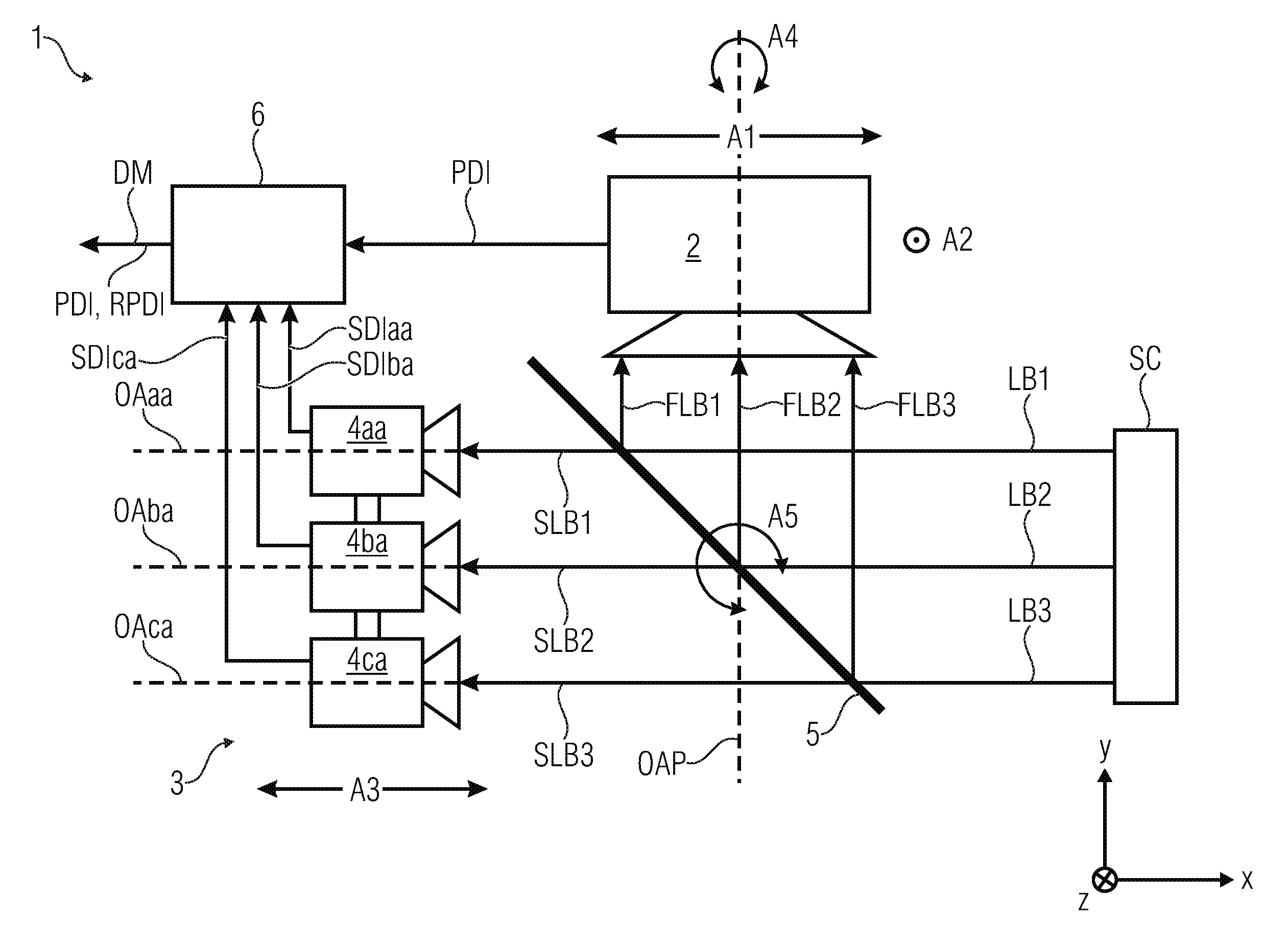
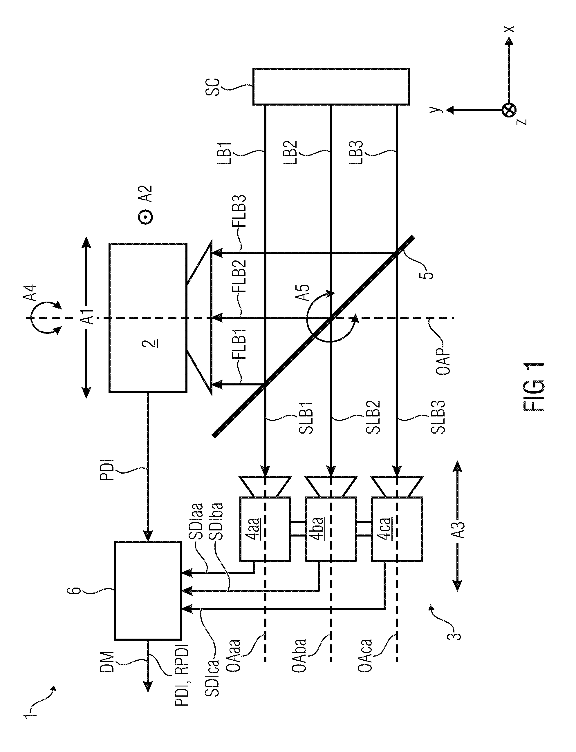
[0070]FIG. 1 illustrates a light-field camera 1 according to the invention in a schematic view.

[0071]The light-field camera for capturing multiple views of a scene SC, the multiple views representing samples of a light-field, the light-field camera 1 comprising:

[0072]a primary camera 2 configured for capturing a primary digital two-dimensional image PDI of the scene SC;

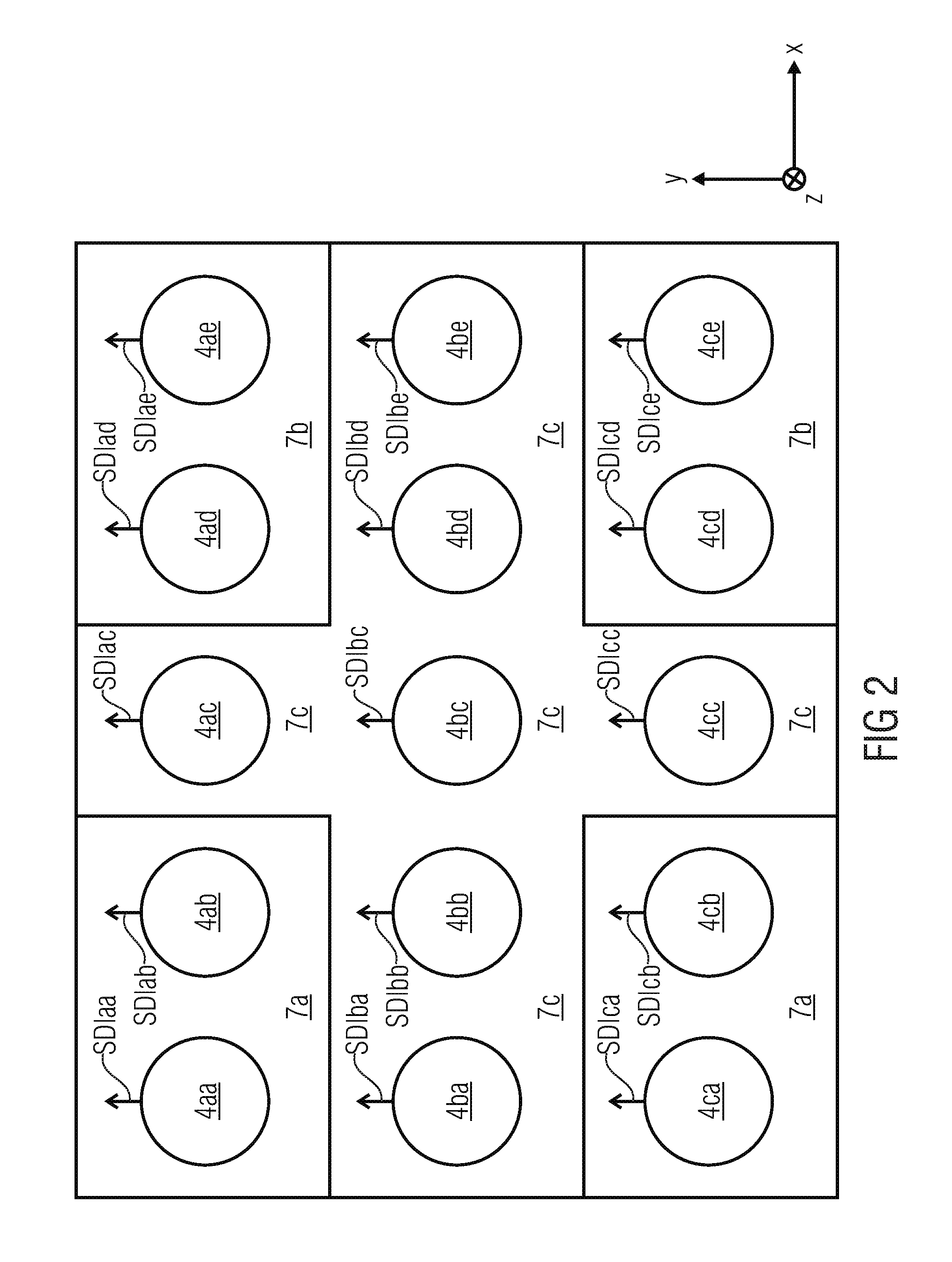
[0073]a two-dimensional camera array 3 comprising a plurality of secondary cameras 4aa . . . 4ce, wherein each of the secondary cameras 4aa . . . 4ce is configured for capturing a secondary digital two-dimensional image SDIaa . . . SDIce of the scene SCI in order to produce at least one set of secondary digital two-dimensional images SDIaa . . . SDIce of the scene;

[0074]a semitransparent mirror 5 arranged in such way that an incident light beam LB1, LB2, LB3 originating from the scene SC is split up in a first partial light beam FLB1, FLB2, FLB3, which is directed to the primary camera 2, and a second partial light be...

second embodiment

[0100]FIG. 3 illustrates a light-field camera 1 according to the invention in a schematic view.

[0101]In the embodiment shown in FIG. 3, the camera array 3 has a fixed position, while the primary camera 2 can be moved in x-, y- and z-direction. In another embodiment, the primary camera 2 is fixed and the camera array 3 can be moved in x-, y- and z-direction. In another embodiment, the camera array 3 can be moved in x- and y-direction, while the primary camera 2 can be moved in y-direction.

[0102]In all these configurations, the mirror 5 can be optionally removed such that the camera array has a direct view on the scene without any reflections or loss of light by the mirror. In another embodiment, the locations of the array 3 and primary camera 2 are interchanged.

[0103]In again another embodiment, some of the mechanical adjustment possibilities are eliminated in order to simplify the construction of the rig. For instance, in FIG. 3 the position of the primary camera 2 might be fixed, t...

third embodiment

[0144]FIG. 9 illustrates a processing unit 6 and a post-processing unit 16 in a schematic view.

[0145]As in the embodiment of FIG. 4 the processing unit 6 comprises a rectification module 8 configured for simultaneously rectifying of the secondary digital two-dimensional images SDIaa . . . SDIce of the set of secondary digital two-dimensional images SDIaa . . . SDIce and the primary digital two-dimensional image PDI by using feature points or checkerboards in order to produce a set of rectified secondary digital two-dimensional images RSDIaa . . . RSDIce and a rectified primary digital two-dimensional image RPDI.

[0146]According to an embodiment of the invention the processing unit 6 comprises a depth information computing module 15 configured for computing a depth information DIMaa . . . DIMce for each of the secondary cameras 4aa . . . 4ce and a depth information DM for the primary camera 2 based on the set of rectified secondary digital two-dimensional images RSDIaa . . . RSDIce an...


PUM


Abstract

The invention provides a light-field camera for capturing multiple views of a scene, representing samples of a light-field, having: a primary camera configured for capturing a primary digital two-dimensional image of the scene; a two-dimensional camera array having a plurality of secondary cameras, each of the secondary cameras being configured for capturing a secondary digital two-dimensional image of the scene to produce at least one set of secondary digital two-dimensional images of the scene; a semitransparent mirror arranged such that an incident light beam originating from the scene is split up in a first partial light beam, directed to the primary camera, and a second partial light beam, directed to the camera array; and a processing unit configured for receiving the primary digital two-dimensional image and the at least one set of secondary digital two-dimensional images and configured for computing depth information for the primary digital two-dimensional image or a digital two-dimensional image corresponding to the primary digital two-dimensional image based on the set of secondary digital two-dimensional images.

Description

CROSS-REFERENCE TO RELATED APPLICATION[0001]This application claims priority from European Application No. 15154934.2, filed Feb. 12, 2015, which is incorporated herein by reference in its entirety.BACKGROUND OF THE INVENTION[0002]Light-field image and video processing offers a much richer variety of image manipulation possibilities compared to traditional 2D images. However, capturing of high-quality light-fields is still unsolved, because a huge number of different views need to be combined with excellent image quality such as dynamic range, color fidelity and resolution.[0003]Traditional 2D-images represent the projection of the three-dimensional world onto a two-dimensional plane. In digital images, this plane is rasterized into a grid of so called pixels. For every visible point in space, a 2D-image records the intensity of one or multiple pixels.[0004]Stereoscopic images extend this principle by recording two different views of a scene. By showing the left captured image to th...

Claims


Application Information

Patent Timeline
IPC IPC(8): H04N5/247G06T7/00
CPCG03B17/568H04N5/247G03B17/561G03B19/07G06T5/007G06T5/50G06T7/0065H04N5/2258H04N5/23232H04N5/355H04N5/3692H04N13/0271G06T7/0051G06T2207/10024G02B27/0075H04N13/243H04N23/60H04N23/73G06T2200/21G06T2207/10052G03B35/10G06T7/557G02B27/144H04N23/45H04N23/743H04N23/741H04N23/90
Inventor ZILLY, FREDERIKKEINERT, JOACHIMZIEGLER, MATTHIASSCHOEBERL, MICHAEL
Owner FRAUNHOFER GESELLSCHAFT ZUR FOERDERUNG DER ANGEWANDTEN FORSCHUNG EV
Why Eureka
Try Eureka