Spin Inducing Arm Pitching Machine

a technology pitching machine, which is applied in the field of spin inducing arm pitching machine, can solve the problems of lack of realism, lack of realistic simulation of human pitcher to batter, lack of prior art wheeled inventions, etc., and achieves the effect of quick adjustment of the spring rate, and reducing the energy input ra

Active Publication Date: 2016-09-01
HART THOMAS
View PDF10 Cites 26 Cited by
  • Summary
  • Abstract
  • Description
  • Claims
  • Application Information

AI Technical Summary

Benefits of technology

[0016]It is another object of the present invention to provide such a ball-throwing machine that is able to interchangeably deliver a variety of different pitches to a variety of different locations at a variety of different speeds without the need to manually readjust the machine between pitches.
[0052]The software and hardware configuration of the subject invention provides users a novel user-friendly, direct method for specifying pitch parameters on any type of machine. These input parameters can easily be used to calculate the individual gripper angle, ball spin rate and / or arm speeds and release point required to generate the selected pitch.

Problems solved by technology

First, since there is no wind-up motion, there is not visual cue to the batter that the pitch is imminent.
Furthermore, lacking the windup and forward motion of an arm, there is lacking a means for the batter to visually see the ball as it is in the process of being pitched.
As a result, these prior art wheeled inventions lack the realistic simulation of a human pitcher to a batter, or of a tennis player serving a ball.
As a result, to set up the machine for the first time in practice, or to vary the type of pitch to the same location still required manual trial-and-error adjustment of the machine by a user, resulting in delays and lack of realism, both detrimental to effective simulation of real-world sport game situations thereby limiting the effectiveness of practicing with these machines.
Another drawback to these prior art methods of programming the machine is it assumes a generic pitch by type, rather than the real-world situation in which all human pitchers have unique nuances, speeds, locations and amounts of spin for a given type of pitch.
The related drawback is there is no ability to alter any parameters and have the ball automatically delivered to a desired location on the plate.
As a result, the prior art did not enable users to quickly and easily program their pitching machines to enable practice against a known pitcher, including one they may face in an upcoming game.
Another large drawback to prior art wheeled pitching machines, is the requirement to speed up or slow down one or more of the drive-wheels to adjust the speed of the pitch.
This can be time consuming as well as energy-intensive, for example if reverse voltage or dynamic braking means are used, resulting in heat-buildup.
While many players prefer the added realism of arm style machines over the more ubiquitous wheel style machines, these arm machines have had a number of limitations.
The prior art arm-type devices do not control the spin of the pitched ball as wheeled machines can, so they cannot throw these various types of pitches with various breaks and spins encountered in actual games.
Another lack of realism in prior art arm machines is due to their attempts to save energy, reduce spring size and weight and reduce the recoiling action of the rotating arm on the stability and durability of the machine, by making the arm itself in the prior art typically so short, 12-18″, it moves so quickly, that the added realism compared to human pitcher is limited.
Furthermore, adjusting pitch speeds on prior art arm machines usually involves adjusting one or more heavy, powerful springs, which is physically difficult, time consuming and not easily repeatable.

Method used


Image

  • Spin Inducing Arm Pitching Machine
  • Spin Inducing Arm Pitching Machine
  • Spin Inducing Arm Pitching Machine

Examples


Embodiment Construction

[0088]All the following descriptions and embodiments relate to the same invention, an arm-type pitching machine which can control the spin, velocity and location of a pitched ball, to the degree and by means the prior art has not achieved nor anticipated. For simplicity, in this specification and claims the words pitch, pitcher and pitching is understood to mean not only pitching a ball to a batter, but also throwing a ball in various ways to a fielder, tennis player and other persons desiring to practice any game, sport or activity involving any object which may be propelled by the subject machine and process.

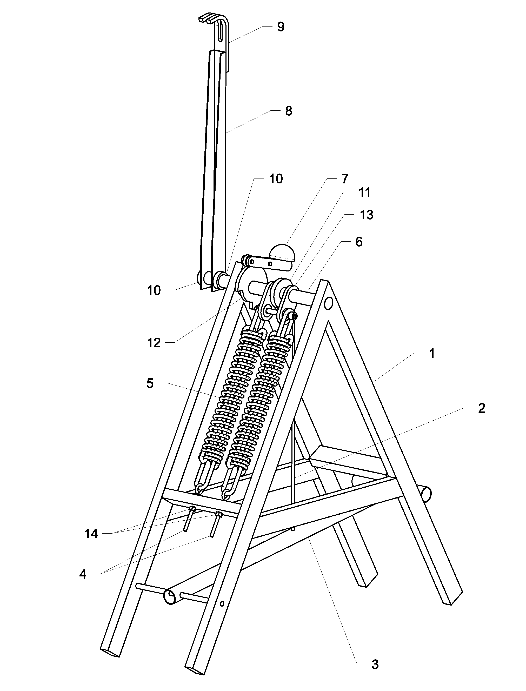
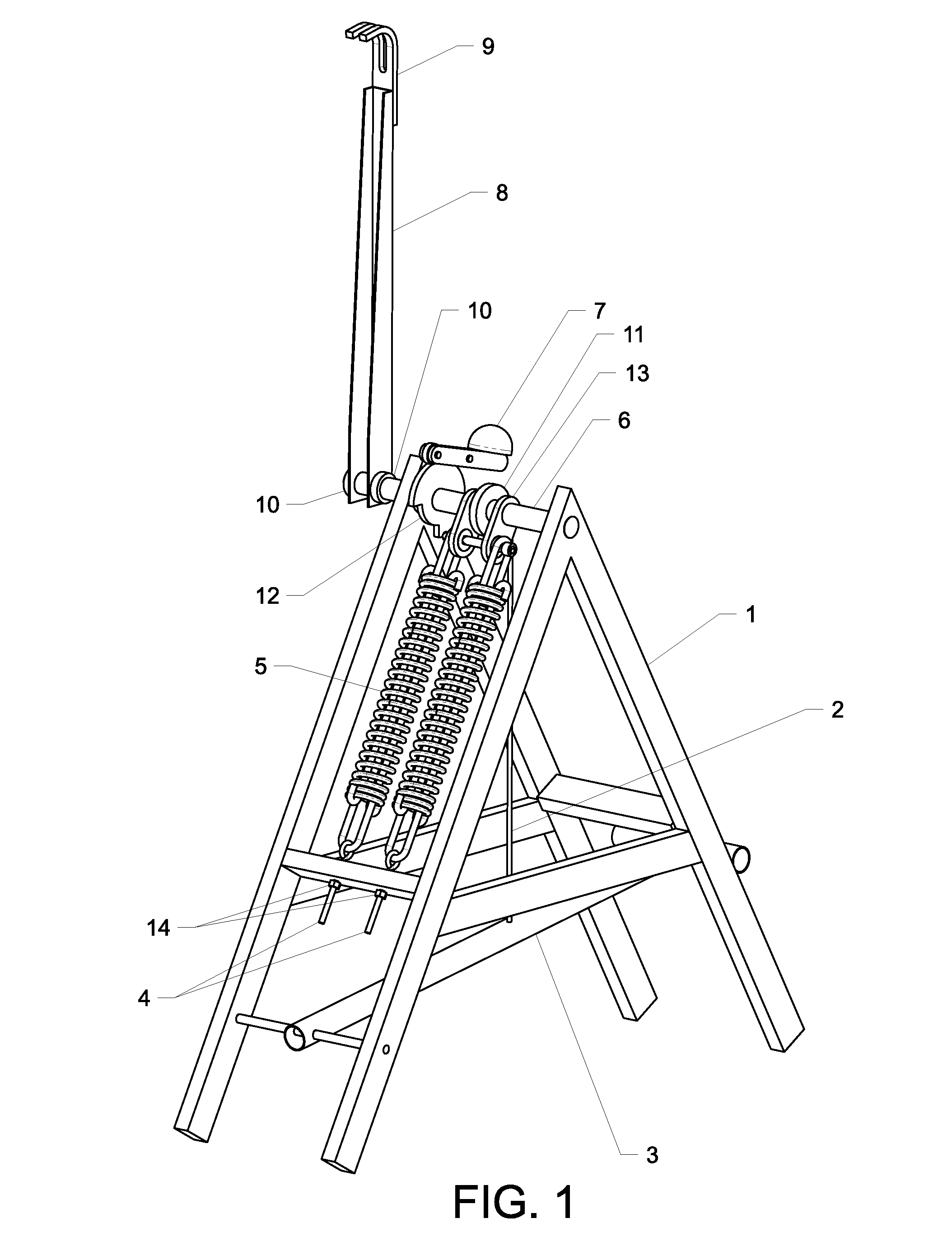
[0089]Turning to FIG. 1, indicating a foot-powered version of the machine, including a basic frame 1, to which is incorporated a cable 2 connected to a foot pedal 3. Connected to the frame are one or more threaded fasteners, such as eyebolts 4, which serve to secure one or more springs 5 which provide the twisting power or torque upon a rotating shaft 6. This twisting power is...


PUM


Abstract

A game ball throwing machine utilizing a rotating arm to pitch a game ball, able to induce a variety of spins and types of pitches interchangeably. The ball thrower includes a base, a support frame attached to the base, rotating arm mechanism attached to the support frame, a source of power rotating the arm, ball holding means attached to the arm, and a human-machine interface which enables control of ball spin, release point, speed and target location. A novel software program integrates the throwing machine, indexing elements and one or more human-machine interface screens, calculating pitch parameters and converting them to machine outputs to enable customization of pitch variety and characteristics to the same or different locations rapidly with a high degree of accuracy, including means to simulate a known pitcher's unique pitch collection.

Description

[0001]This is a Non-Provisional Utility patent application for the disclosure of a “SPIN INDUCING ARM PITCHING MACHINE.”[0002]A portion of the disclosure of this patent document, including the computer program listing, contains material that is subject to copyright protection. The copyright owner has no objection to the reproduction of the patent document or the patent disclosure, as it appears in the U.S. Patent and Trademark Office patent file or records, but otherwise reserves all copyright rights whatsoever.CROSS-REFERENCES TO RELATED APPLICATIONS[0003]This application claims benefit of the following patent application(s) which is / are hereby incorporated by reference: Automatic Ball Pitching Machine, Application Number 62098698 filed 31 Dec. 2014STATEMENT REGARDING FEDERALLY SPONSORED RESEARCH OR DEVELOPMENT[0004]Not ApplicableREFERENCE TO SEQUENCE LISTING OR COMPUTER PROGRAM LISTING APPENDIX[0005]See Specification Appendix for computer listing program as a reduction to practice...

Claims


Application Information

Patent Timeline
Patent Type & Authority Applications(United States)
IPC IPC(8): A63B69/00A63B69/40
CPCA63B69/0002A63B69/406A63B2069/0008A63B2225/50A63B2225/093A63B69/0053A63B71/0622A63B2069/0011A63B2071/065A63B2071/0675A63B2071/0694A63B2225/09A63B2243/0025A63B2102/02A63B2102/18A63B2102/182A63B69/40A63B2069/402A63B2069/401A63B2225/74A63B69/408F41B3/03
Inventor HART, THOMAS J.
Owner HART THOMAS
Why Eureka
Try Eureka