Automatic vacuum drying device

a vacuum drying device and vacuum technology, applied in the direction of drying machines with progressive movements, sustainable manufacturing/processing, final product manufacturing, etc., can solve the problems of difficult to realize seamless connections between vacuum drying devices, poor processing efficiency of drying devices, and inability to control the humidity and temperature of dry air in vacuum conditions. achieve the effect of high vacuum conditions, efficient drying, and simple structur

Active Publication Date: 2016-09-08
SHENZHEN TIME HIGH TECH EQUIP
View PDF0 Cites 17 Cited by
  • Summary
  • Abstract
  • Description
  • Claims
  • Application Information

AI Technical Summary

Benefits of technology

[0015]An automatic vacuum drying device comprises a drying oven, a heating device used to heat the drying oven, a vacuum extraction device used to evacuate the drying oven, a nitrogen input device used to input nitrogen into the drying oven, and a transporting device located inside the drying oven and used to transport materials, two first openings are located at two opposite sides of the drying oven, an automatic sealing door is mounted on at least one of the first openings, the automatic sealing door includes a first door plank and a second door plank parallel to the first door plank, an elevator structure is located between the first door plank and the second door plank, the elevator structure is used to lift the first door plank and the second door plank, at least two articulation elements are located between the first door plank and the elevator structure, one end of each articulation element is connected with the first door plank, an opposite end of each articulation element is connected with the elevator structure, at least two another articulation elements are also located between the second door plank and the elevator structure, one end of each another articulation element is connected with the second door plank, an opposite end of each another articulation element is connected with the elevator structure, a first roller is located at a bottom of the first door plank, a first slant surface with left higher than right is located bellow the first roller, a second roller is located at a bottom of the second door plank, a second slant surface with left higher than right is located bellow the second roller. The elevator structure can drive the first door plank and the second door plank to move down when the elevator structure descends, the first roller moves downward along the first slant surface, and the second roller moves downward along the second slant surface simultaneously, the first door plank will move toward a processing equipment which can be regarded as a previous process of the automatic sealing door and resist an opening of the processing equipment, the second door plank will move towards one second opening having the automatic sealing door and finally resist on the second opening, such that, the opening of the processing equipment which is the previous process of the automatic sealing door is sealed, and the second opening having the automatic sealing door is also sealed, the working process of opening the automatic sealing door is opposite to the working process of closing the automatic sealing door. Such that the first openings of a plurality of automatic vacuum drying devices can be docked to form the automatic vacuum drying production line, the transporting device can be used to transport materials among the automatic vacuum drying devices, the vacuum extraction device is used to evacuate the drying oven, the nitrogen input device is used to input nitrogen into the drying oven after the drying oven is evacuate, then the heating device starts to dry materials located inside the drying oven. The automatic vacuum drying devices can be set different vacuum degrees, drying temperatures, and drying times, such that automatic vacuum drying devices can drying efficiently, and and control the dry humidity and the temperature maintain highly uniform in vacuum condition. The side surface of the automatic vacuum drying device having the first opening sealed by the automatic sealing door further has the cavity used to receive the first door plank, the second door plank and the elevator structure, two second openings are formed on two opposite sides of the cavity, one second opening closing to the drying oven is connected with one first opening formed on the drying oven and closing to the cavity, the above structure can omit a distance between the automatic sealing door and the opening of the processing equipment used in the previous process, the second opening of the cavity far away the drying oven is directly connected with the opening of the processing equipment used in the previous process, there is no need to set a cover to be coiled around the automatic sealing door to ensure the vacuum degree of the automatic vacuum drying device, the cavity is separated from the outside to ensure the vacuum degree of the automatic vacuum drying device, and when the automatic sealing door is opened, the vacuum degree of the automatic vacuum drying device is not affected, such that the automatic vacuum drying device avoids vacuuming and inputting nitrogen again, to save energy and improve efficiency. When the elevator structure drives the first door plank and the second door plank to move down to the limit position, the first door plank and the second door plank resist the two second openings from the inner side of the cavity respectively, a working mode which is defined as one elevator structure drives the first door plank and the second door plank, another working mode which can be defined as one elevator structure drives one door plank, the working mode of the present invention saves one elevator system, that is, only one elevator system can seal two openings, such that the structure is simple and the cost is reduced. The elevator structure includes the rack and the first gear corresponding to the rack, the first door plank and the second door plank are connected with the rack through the articulation elements, the first gear is driven by motor, the driving mode can not only provide enough pressing force to ensure that the first door plank and the second door plank can be tightly attached with the second openings respectively, the driving mode can be operated stably under high temperature. The automatic vacuum drying device further includes a guided rail which is parallel to the rack, the rack further has a plurality of guided rollers corresponding to the guided rail, the guided rail and the guided rollers can ensure that the first door plank and the second door plank always move up and down straightly, such that when the first door plank and the second door plank attach with the second openings, the first door plank always parallels to the second door plank, no angle can be existed between the first door plank and the second door plank, such that the first door plank and the second door plank can be tightly attached with the second openings to ensure the sealing effect of the drying oven, and improve the effect of the vacuum drying. The left side of the first door plank has sealant tape, the right side of the second door plank also has sealant tape, the sealant tapes can ensure that when the first door plank closes with the second door plank, the first door plank and the second door plank can attach with the second openings more tightly, such that the inner of the drying oven can be completely separated from the outside to improve the vacuum drying effect. The heating device includes a plurality of heating bodies located at the outside of the drying oven, each heating body includes an aluminum main body and a heating element located inside the aluminum main body the aluminum main body includes the plate and the cover attached with the plate, the groove is located on the plate, the heating element is located in the groove. The heating device is easy to be installed and repaired, and the heating efficiency and the heating uniformity are both good. The transporting device includes a plurality of second gears located in the drying oven, the geometry axis of each second gear is parallel to the bottom surface of the drying oven and the plane of the first openings simultaneously, the second gears are driven by a motor, the automatic vacuum drying device further includes a plurality of guided ways located in the drying oven, the guided ways are perpendicular to the plane of the first openings, the rack corresponding to the second gears is located at the bottom of the material car, the rolling of the gears can drive the material car to move in the drying oven, such that the materials can be transported among the automatic vacuum drying device, the bottom of the material car has guided rollers corresponding to the guided rail, such that the material car can run stably, and would not contact with the inner wall of the drying oven, and when the automatic vacuum drying devices form the e automatic vacuum drying producing lines, the material car can move smoothly through the automatic vacuum drying devices by aligning the guided rails.

Problems solved by technology

The traditional vacuum drying device mainly includes a single vacuum drying oven, and electronic components needed to be dried are transported to the vacuum drying device through a material car, the traditional vacuum drying device is poor in processing efficiency, and cannot control the dry humidity and the temperature maintain highly uniform in vacuum condition.
However, how to realize seamless connections among the vacuum drying devices is always a difficult problem, one solution solve this problem is setting automatic air-tight doors on the vacuum drying devices, such that the vacuum drying devices can be connected with each other seamlessly, however, the traditional vacuum drying devices cannot solve the problem.

Method used


Image

  • Automatic vacuum drying device
  • Automatic vacuum drying device
  • Automatic vacuum drying device

Examples


Embodiment Construction

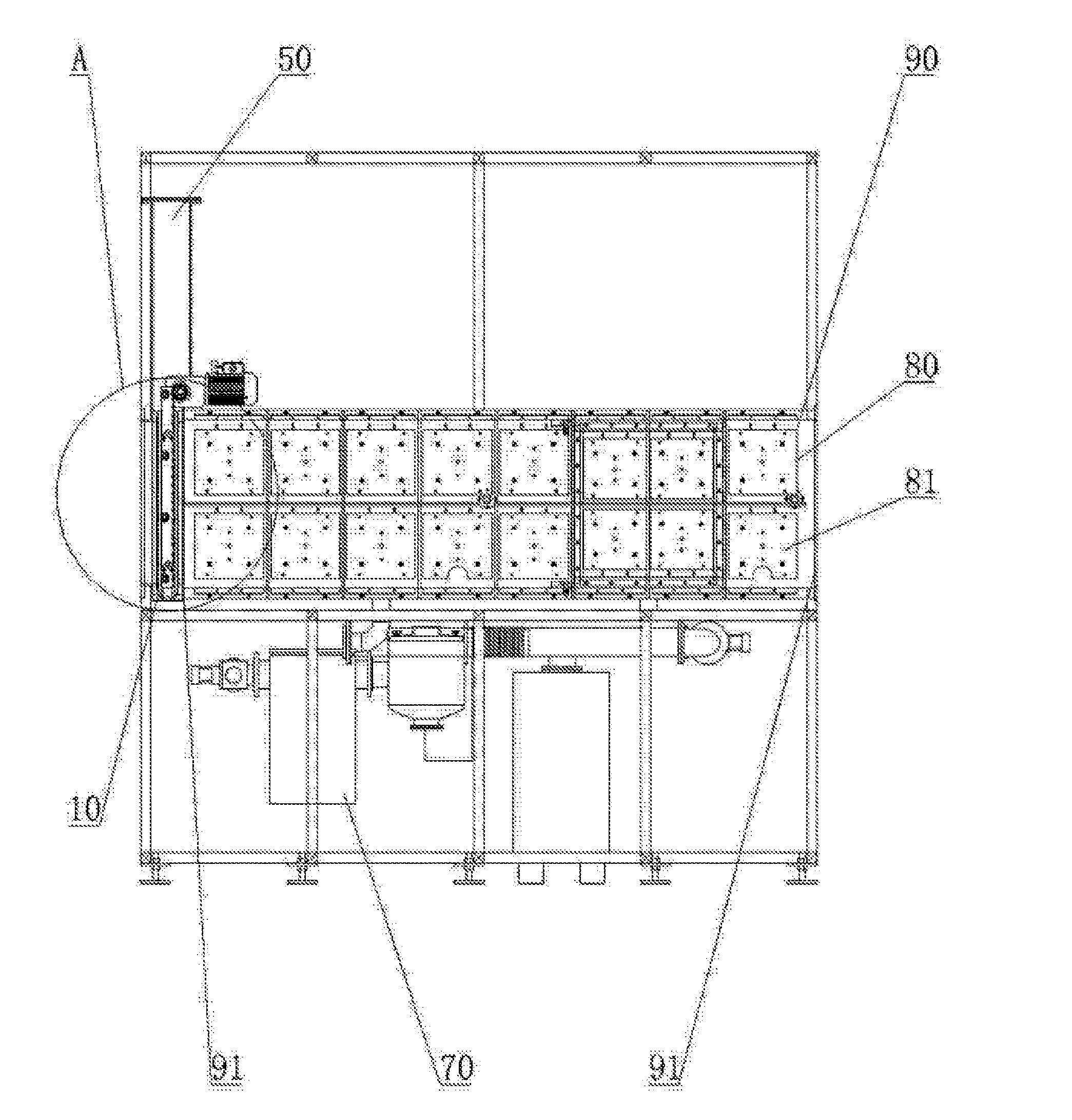
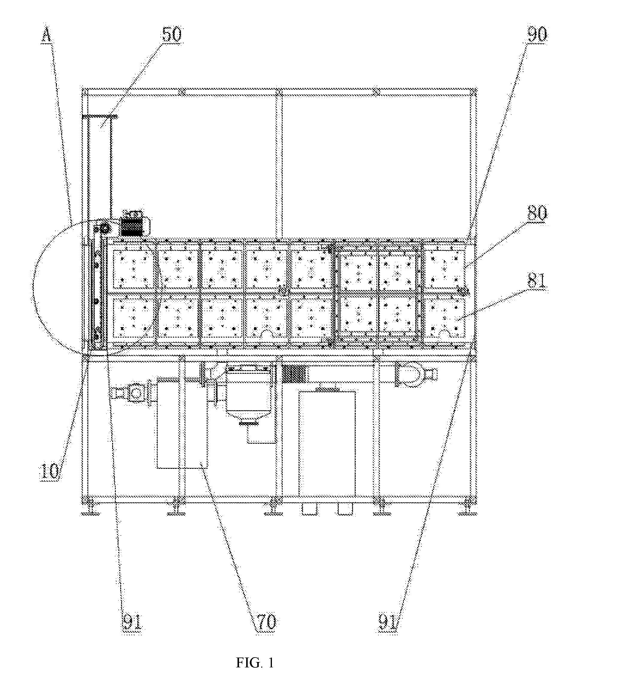
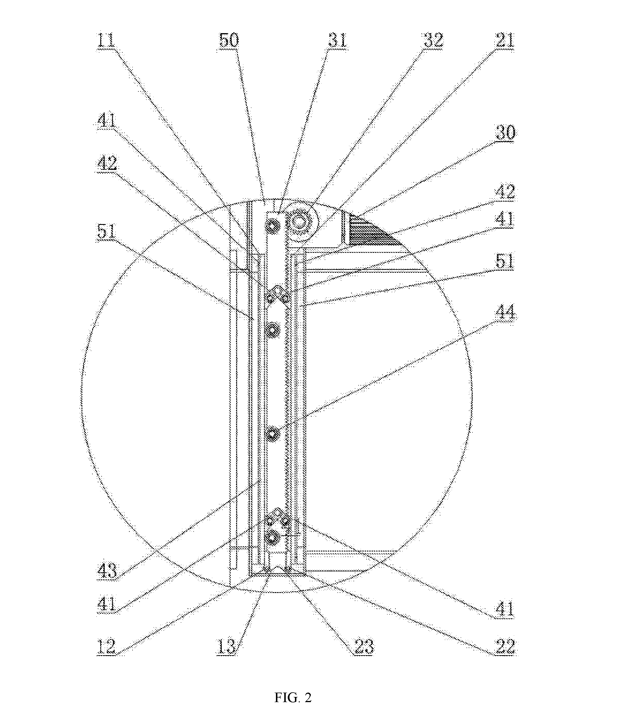
[0021]Referring to FIGS. 1-3, an automatic vacuum drying device, includes a drying oven 90, a heating device 80 used to heat the drying oven 90, a vacuum extraction device 70 used to evacuate the drying oven 90, a nitrogen input device used to input nitrogen into the drying oven 90, a transporting device 60 located inside the drying oven 90 and used to transport materials. And the heating device 80 can be a heating plate which includes an aluminium plate and at least one electric heating pipe located in the aluminium plate, then the heating plate can cover an outside of the drying oven 90; the heating device 80 can also be another heating plate which includes another aluminium plate and at least one far infrared heating pipe located in the another aluminium plate, the the another heating plate can cover the outside of the drying oven 90; at the same time, the heating device 80 can also be a heating plate which includes an aluminium plate and at least one high temperature electric he...


PUM

PropertyMeasurementUnit
processing efficiencyaaaaaaaaaa
dry humidityaaaaaaaaaa
temperatureaaaaaaaaaa

Abstract

An automatic vacuum drying device comprises a drying oven, a heating device used to heat the drying oven, a vacuum extraction device used to evacuate the drying oven, a nitrogen input device used to input nitrogen into the drying oven, and a transporting device located inside the drying oven and used to transport materials, two first openings are located at two opposite sides of the drying oven, an automatic sealing door is mounted on at least one of the first openings, the automatic sealing door includes a first door plank and a second door plank parallel to the first door plank, an elevator structure is located between the first door plank and the second door plank, the elevator structure is used to lift the first door plank and the second door plank. The automatic vacuum drying devices can form an automatic vacuum drying production line conveniently, and the automatic vacuum drying production line has high degree of automation, and high processing efficiency, such that it is possible to drastically improve the vacuum drying efficiency.

Description

TECHNICAL FIELD[0001]The present invention relates to an automatic vacuum drying device, especially relates to an automatic vacuum drying device which can form an automatic vacuum drying production line conveniently, and the automatic vacuum drying production line has high degree of automation, and high processing efficiency.BACKGROUND ART[0002]A vacuum drying process is an important producing process during the electronic components manufacturing processing. The vacuum drying process can reduce water contained in the electronic components, such that the electronic components can meet the using requirement. The vacuum drying process is mainly applied to the manufacturing processes of the electronic components, especially applied to the manufacturing processes of the supercapacitor or the manufacturing processes of the lithium battery. The traditional vacuum drying device mainly includes a single vacuum drying oven, and electronic components needed to be dried are transported to the ...

Claims


Application Information

Patent Timeline
Patent Type & Authority Applications(United States)
IPC IPC(8): F26B5/04F26B25/12F26B23/06H01M10/058H01G11/84H01G13/04H01M10/0525F26B15/12F26B21/14
CPCF26B5/042F26B15/12F26B25/12F26B23/06H01M10/058H01G11/84H01G13/04H01M10/0525F26B21/14F26B5/04F26B7/00H01M10/052Y02E60/10Y02P70/50Y02E60/13
Inventor TIAN, HANRONG
Owner SHENZHEN TIME HIGH TECH EQUIP
Why Eureka
Try Eureka