Cable barrier post anchoring device and related method

a technology of anchoring device and cable barrier, which is applied in the direction of machine supports, applications, roads, etc., can solve the problems of too high risk of accidents, more accidents, and significant damage and/or injury to the property of others, and achieve the effect of less time-consuming and costly installation and/or repair

Active Publication Date: 2013-03-19
RONNKVIST THOMAS M
View PDF10 Cites 0 Cited by
  • Summary
  • Abstract
  • Description
  • Claims
  • Application Information

AI Technical Summary

Benefits of technology

[0009]One principal object of the present invention is therefore to overcome the deficiencies of the safety barrier systems described above and provide an improved cable barrier system that is less time consuming and costly to install and / or repair.
[0010]Another object of the present invention is to enhance vehicle, passenger and road worker safety by providing a more efficient apparatus and method for installing and repairing roadway cable barrier systems that minimizes traffic disruption and the potential for injury incident thereto.
[0011]It is still a further object of the present invention to provide a roadway cable barrier system that is highly stable and that can be readily installed and repaired when necessary with minimal disruption to the stability and integrity of the surrounding soil and little or no soil spoilage, thereby enhancing the stability of the cable barrier system.

Problems solved by technology

As the number of vehicles has increased on the roadways, so too has the risk of accidents.
These barriers help to prevent errant vehicles from leaving the roadway and / or crossing lanes into oncoming traffic, thus causing significant damage and / or injury to the property of others.
While these more permanent massive concrete barriers are helpful in preventing vehicles from entering oncoming traffic lanes, they do not prevent vehicles from rebounding back into the original lane of traffic, and have been known to frequently cause more accidents in this manner.
While effective, installing this system is complicated and time consuming.
Moreover, most Department of Transportation (DOT) regulations now require the removal of all “spoils” caused by auguring the holes for the cement anchors, which adds additional time, cost and traffic disruption to the installation process.
As is evident, multiple trips to the installation site result in increased installation time and consequent traffic diversion / stoppage.
Importantly, it also significantly increases the potential for accident and injury to vehicles on the roadway, as well as the roadway workers installing such systems.
Other cabling systems utilizing pre-cast socketed concrete footings are also available, but such systems are less desirable in that they require larger holes to be dug for installation of the pre-cast footings, create more potential spoilage, and are less stable due to greater soil disruption.
For proper installation, significant and time consuming packing of the soil around the pre-cast footing is required to stabilize each line post before stringing the cabling system.
While such systems are typically easier and less time consuming to install, again their anchoring systems are generally less stable and more prone to damage upon impact by a vehicle.
Upon such an impact by a vehicle, not only is damage typically caused to the vehicle and possibly the vehicle's passengers, but oftentimes the cable barrier system itself undergoes significant damage.
In most cases, the cabling systems become damaged and the line posts are oftentimes bent severely beyond repair, thus requiring replacement.
More significantly, however, is the fact that oftentimes the sockets that are fixed within the concrete footings are badly damaged and incapable of receiving another line post, or the concrete footing itself has been shifted out of proper alignment.
Such replacement causes a further significant disruption of the surrounding soil, thereby reducing the stability of the unit under repair.
Obviously, such required frequent repairs are tedious, time consuming and expensive.
More time is spent diverting and disrupting traffic flow, and the potential for accident and injury to others also increases.

Method used


Image

  • Cable barrier post anchoring device and related method
  • Cable barrier post anchoring device and related method
  • Cable barrier post anchoring device and related method

Examples


Embodiment Construction

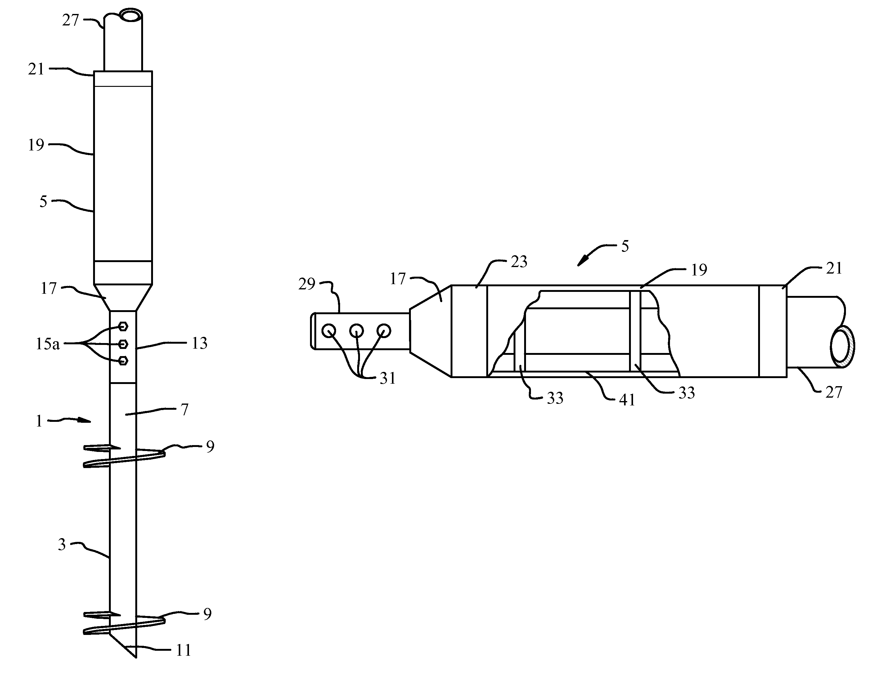
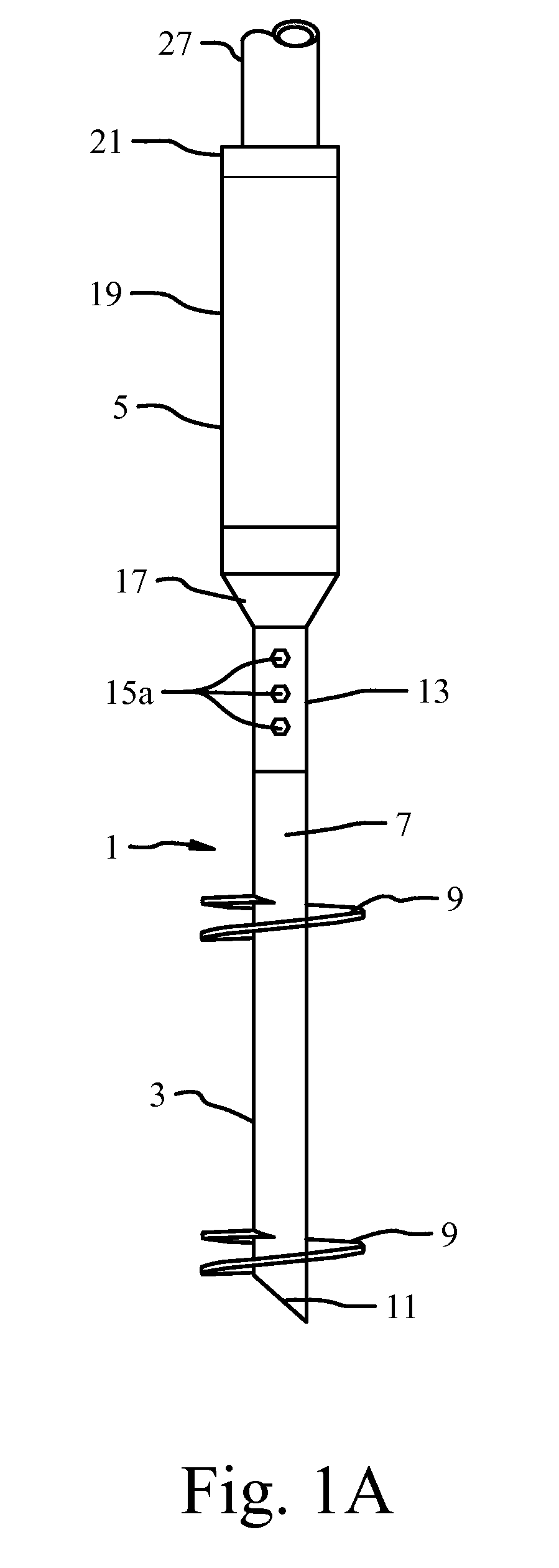
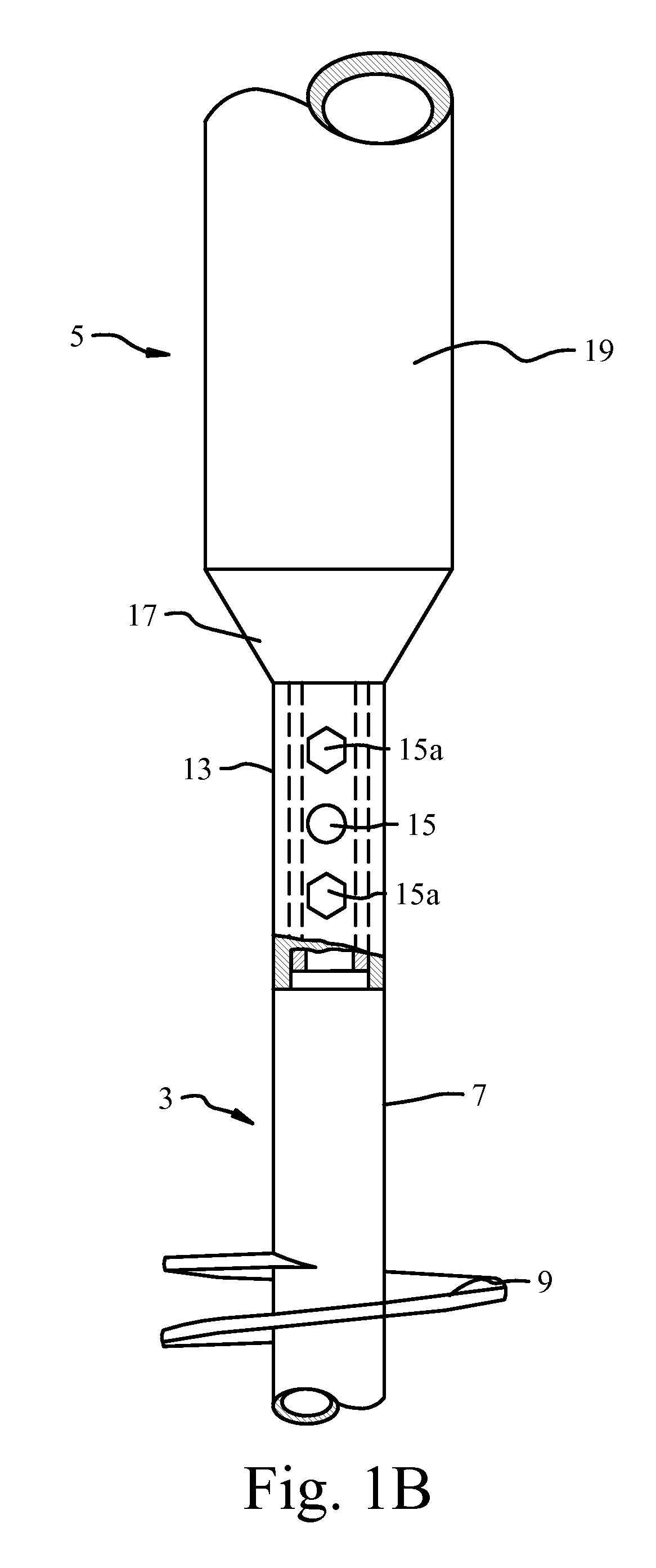
[0028]As shown in FIG. 1A, in accordance with the present invention, a line post anchoring device 1 for a cable barrier system is shown. The anchoring device 1 is comprised generally of a lower helical anchor 3 to which a detachable line post socket member 5 is secured. The helical anchor 3 includes in general a main tubular drive shaft section 7 to which one or more helical flights or plates 9 are permanently affixed, as by welding. The lower end of drive shaft 7 tapers to a point 11 to facilitate penetration of the ground upon insertion of the anchor 3. Point 11 may take the form of and be constructed in any of a variety of ways, but in the preferred embodiment shown in FIG. 1A, it is formed by cutting the lower end of the drive shaft 7 at about a forty-five (45) degree angle, and leaving the end hollow.

[0029]Flights 9 are helically shaped to cause anchor 3 to be screwed into the ground upon rotation of the drive shaft 7. Each flight 9 secured to the main drive shaft section 7 may...


PUM

PropertyMeasurementUnit
angleaaaaaaaaaa
tensile strengthaaaaaaaaaa
depthaaaaaaaaaa

Abstract

A line post anchoring device for a roadway cable barrier system includes a lower helical anchor to which a detachable line post socket member is secured. The helical anchor and line post socket of each line post anchoring device have mating coupling sections that are preassembled and hydraulically screwed into the ground in a single operation. Each socket includes interior guide plates for properly guiding and positioning a line post therein, such that the cabling system can be effectively strung under tension at the same time the anchoring devices are installed in the ground. Damaged sockets are easily replaced with minimal disruption to the surrounding soil by backing the helical anchor out of the ground only so far as necessary to detach and replace the damaged socket, and then reinserting the helical anchor in the same location. There is no delay or multiple operations required for installation or repair, thus enhancing roadway safety by minimizing traffic disruptions and possible accidents incident thereto.

Description

CROSS REFERENCE TO RELATED APPLICATIONS[0001]This application is an application for a patent which is also disclosed in Provisional Application Ser. No. 61 / 360,964, filed on Jul. 2, 2010 by the same inventor, namely Thomas M. Ronnkvist, and entitled “CABLE BARRIER POST ANCHORING DEVICE AND RELATED METHOD,” the benefit of the filing date of which is hereby claimed.BACKGROUND OF THE INVENTION[0002]The present invention relates generally to the art of highway safety barriers and methods of installing same. More particularly, the present invention relates to cable barrier systems used along edges and in the medians between roadways and the like, and methods of erecting such barriers.[0003]As the number of vehicles has increased on the roadways, so too has the risk of accidents. Consequently, concern over vehicle safety, as well as the safety of vehicle passengers and roadway workers, has also increased. As one means of protection, attempts have previously been made to erect safety barri...

Claims


Application Information

Patent Timeline
Patent Type & Authority Patents(United States)
IPC IPC(8): H01Q1/12
CPCE01F15/06E04H12/2223E02D27/42Y10T29/49826
Inventor RONNKVIST, THOMAS M.
Owner RONNKVIST THOMAS M
Why Eureka
Try Eureka