Electronic vaporization device

a technology of electronic vaporization and electronic device, which is applied in the direction of machines/engines, heater elements, tobacco, etc., can solve the problems of inability to control the heating and combustion of existing devices, devices that produce toxic, tarry and carcinogenic by-products, and impart bitter and burnt taste to the mouth of users

Inactive Publication Date: 2016-09-15
JUUL LABS INC
View PDF38 Cites 96 Cited by
  • Summary
  • Abstract
  • Description
  • Claims
  • Application Information

AI Technical Summary

Benefits of technology

[0017]These devices may provide a mouthpiece made of a high temperature food-safe material, such as ceramic, glass, or high temperature plastics known as PEI resin (brand name Ultem). However, suitable plastic or wood, etc., could also be used but would additionally require an insulating material that would prevent excessive heat reaching the user's lips.
[0020]These devices and systems may also provide a heater which is separated from the vapor chamber by an insulating medium such as ring made of PTFE, ceramic or other insulating material and thereby preventing the exhaust gases produced by the heater from entering and contaminating the vapor in the vaporization chamber collected for inhalation.
[0022]In variations including a cartridge (e.g., of tobacco), the tobacco cartridge may be formed and shaped for easier insertion into the heating chamber and to snugly fit into the cavity of the heating chamber for improved thermal conduction and vaporization. The cartridges may be formed and wrapped into wrapper which does not produce significant amount of harmful gases.
[0024]In one aspect, a resistive heating element and thermistor to monitor and precisely control vaporization temperature are disclosed for use in a device for aerosolizing a material. In some embodiments, the heating element comprises an electronic circuit with power transistor to drive the heater. In certain embodiments, the tail of the electronic circuit solders to a PCB (printed circuit board). In some embodiments, the device comprises aerogel insulation to maintain efficiency and low exposed surface temperature. In certain embodiments, the aerogel is a silica aerogel with reinforcing fibers (e.g., Pyrogel 2250 flexible aerogel blanket). In some embodiments, the device comprises a single button interface wherein the single button interface provides means for on, off and wake from sleep (e.g., pressed to begin heating, turn off heating, and wake from standby mode).
[0028]In another aspect provides an electronic stand-alone vaporizer device for use with loose leaf tobacco and / or other botanicals. In some embodiments, the device comprises a mouthpiece that retracts from said device with a push-push mechanism. In some embodiments, the push-push mechanism also turns the device on via a magnet embedded in the mouthpiece and a hall effect sensor on the PCB (printed circuit board). In certain embodiments, the mouthpiece comprises a compression spring, a leaf spring and a stainless steel tube attached to the mouthpiece with a catch groove and a toggle slider. In some embodiments, the device comprises a magnetic on / off control using reed or hall effect switch. In certain embodiments, the magnetic control is integrated into mouthpiece to eliminate additional buttons. In some embodiments, the mouthpiece adapts push-push mechanism for mouthpiece withdrawal and / or retraction. In some embodiments, the device comprises a magnetic lid to cover vaporization chamber. In some embodiments, the device comprises a thermally conductive shell to distribute excess heat and maintain low exposed surface temperature. In some embodiments, the device comprises a button-operated temperature selection with visual, audible indicator, and / or other sensory output (e.g. vibration). In some embodiments, the mouthpiece is integrated into the device with a hinge, or other mechanism (e.g., a string, or the like). In some embodiments, the vaporization device comprises a thin wall metal heating chamber. Thin walls allow for low thermal mass and thus fast startup. In some embodiments, the devices comprise a tilting lid using magnetic or snap attachments for the lid to stay in its closed position to prevent accidental opening. The tilting lid has no visible removal button.

Problems solved by technology

However, existing devices used have no control of heating and combustion of the tobacco products.
The devices tend to produce toxic, tarry and carcinogenic by-products which are harmful and also impart a bitter and burnt taste to a mouth of a user.
This is because many of the harmful analytes, such as Hoffman analytes, obtained from smoking are received due to the burning of the material.
A difficulty of developing and marketing a device that can deliver an aerosolized tobacco product is catering to the user in terms of visual and physical appeal of use.

Method used


Image

  • Electronic vaporization device
  • Electronic vaporization device
  • Electronic vaporization device

Examples


Embodiment Construction

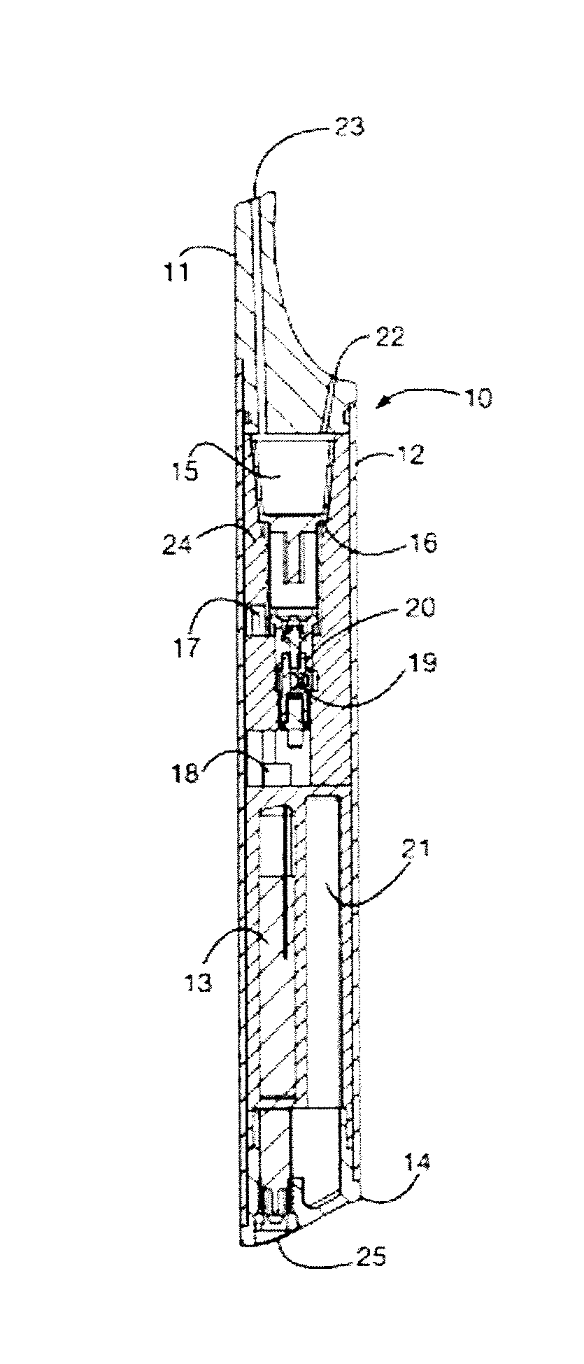
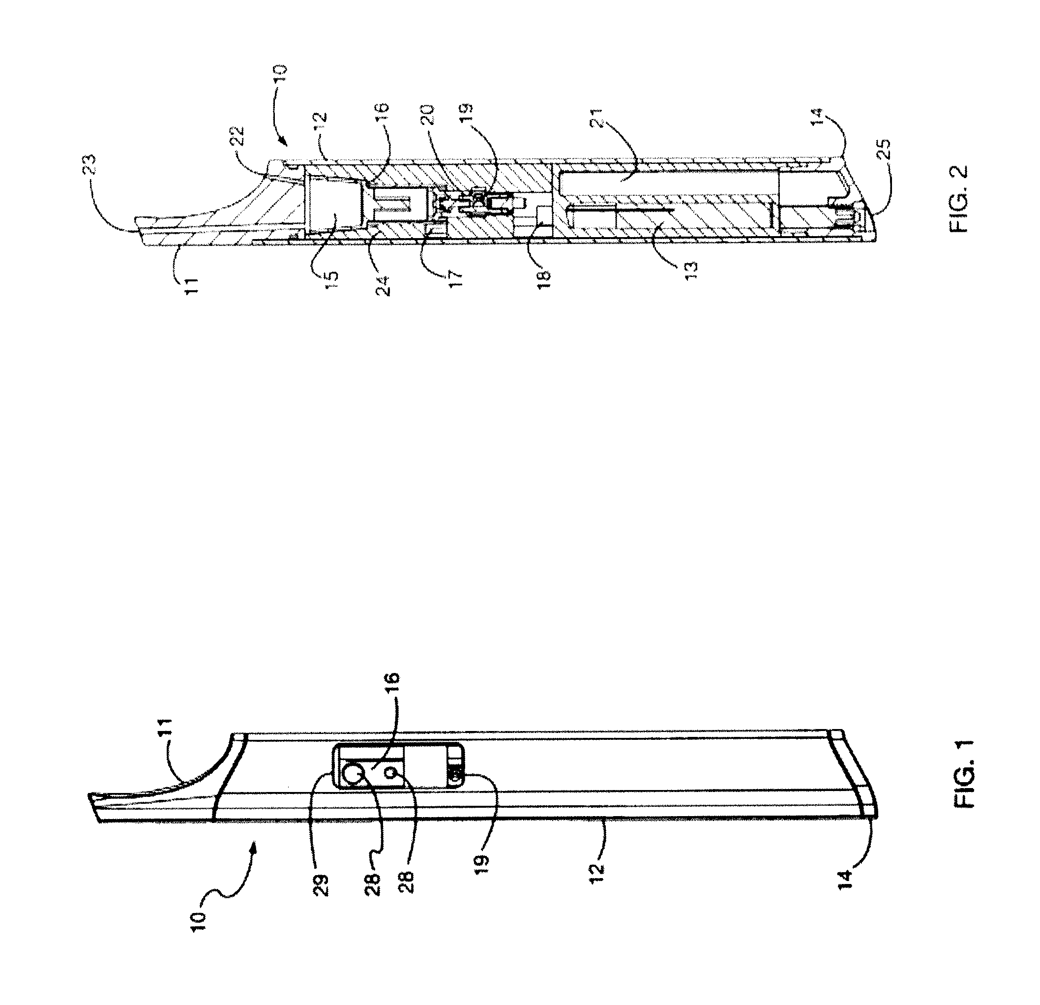
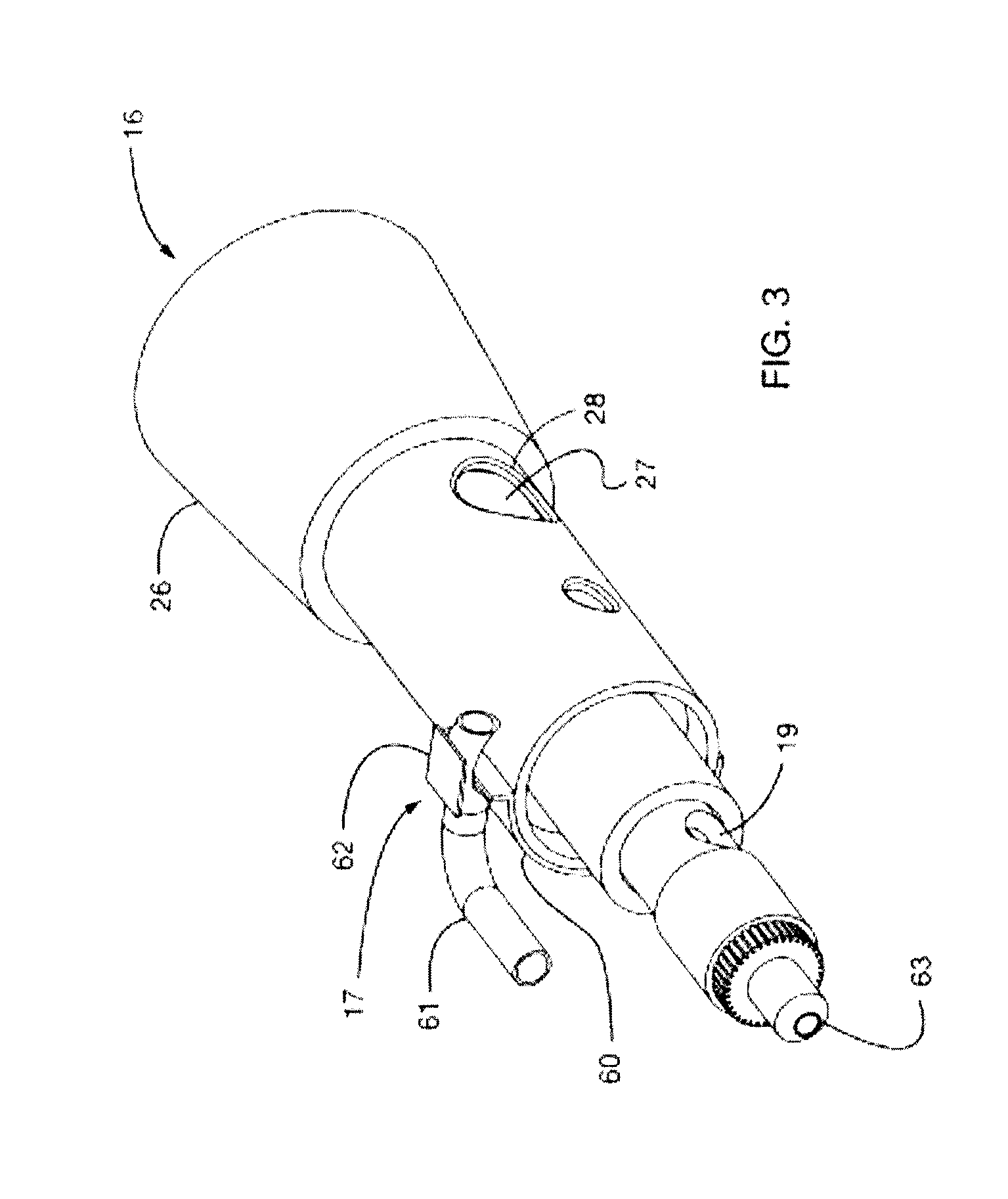
[0078]Referring to FIG. 1 and FIG. 2, the exterior of the device 10 comprises a mouthpiece 11, a tubular case 12, and the base 14 of a butane tank 21. The mouthpiece is removable and creates an airtight seal with the interior of the case. With the mouthpiece removed, a tobacco cartridge (FIG. 5) is introduced to vaporization chamber 15 of a heater 16. The mouthpiece is then reinserted to close the device. Thus, as shown in FIGS. 1 and 2, removal of the mouthpiece exposes the vaporization chamber and replacement of the mouthpiece closes the vaporization chamber.

[0079]The mouthpiece is made of a high-temperature and food-safe material such as ceramic, glass, or various high-temperature plastics such as PEI resin (brand name Ultem). Design is simplified by use of high temperature materials, but standard plastics or wood, etc., could also be used with the addition of an insulating component that prevents any excessive heat from reaching the user's lips.

[0080]To activate the device, the ...


PUM


Abstract

Portable devices for generating an inhalable vapor that include an elongate cylindrical body that may have an oval cross-section, an oven configured to fit within the body and to hold a vaporizable material, a detachable mouthpiece covering the oven, a single-button interface comprising a single button that is configured to be pressed to begin heating, select a heating temperature, and turn off heating and one or more light emitting diode (LED) indicator configured to show information about the status of the device, including a user-selectable temperature setting.

Description

CROSS REFERENCE TO RELATED APPLICATIONS[0001]This application claims priority as a continuation-in-part of U.S. patent application Ser. No. 13 / 587,416, filed on Aug. 16, 2012, titled “LOW TEMPERATURE ELECTRONIC VAPORIZATION DEVICE AND METHODS”, Publication No. US-2013-0042865-A1, which claims priority to U.S. Provisional Patent Application No. 61 / 524,308, filed on Aug. 16, 2011, titled “LOW TEMPERATURE ELECTRONIC VAPORIZATION DEVICE AND METHODS”. Each of these patents and patent applications are herein incorporated by reference in their entirety.[0002]This patent application also claims priority as a continuation-in-part of U.S. patent application Ser. No. 13 / 837,438, filed on Mar. 15, 2013, titled “LOW TEMPERATURE ELECTRONIC VAPORIZATION DEVICE AND METHODS”, Publication No. US-2013-0312742-A1 which is herein incorporated by reference in its entirety.INCORPORATION BY REFERENCE[0003]All publications and patent applications mentioned in this specification are herein incorporated by re...

Claims


Application Information

Patent Timeline
Patent Type & Authority Applications(United States)
IPC IPC(8): A24F47/00H05B3/42H02J7/00H05B3/06A24F40/20A24F40/40A24F40/60A24F40/90
CPCA24F47/008H02J7/0044H05B3/42H05B3/06A61M15/06A61M2016/0024A61M2205/332A61M2205/3368A61M2205/581A61M2205/582A61M2205/8206A61M2205/8237A61M2209/084A61M11/007A61M11/042A61M15/0023A61M15/0025A61M15/0026F04C13/00A24F40/60A24F40/40A24F40/90A24F40/20
Inventor MONSEES, JAMESBOWEN, ADAMMYALL, PATRICK A.HUNTER, KRISTA
Owner JUUL LABS INC
Why Eureka
Try Eureka