Medical apparatus for radiotherapy and ultrasound heating

a technology of medical equipment and ultrasound, applied in the field of radiation beam therapy, to achieve the effect of reducing radiation effect and reducing radiation radiation radiation radiation in the target zon

Inactive Publication Date: 2016-09-15
KONINKLJIJKE PHILIPS NV
View PDF0 Cites 21 Cited by
  • Summary
  • Abstract
  • Description
  • Claims
  • Application Information

AI Technical Summary

Benefits of technology

[0028]Execution of the machine-executable instructions further cause the processor to generate radiation control command data for controlling the radiation beam therapy system to irradiate the target zone using the planning thermal distribution and the treatment plan. The radiation control command data is executable to cause the radiation source to reduce irradiation of the target zone when more than a predetermined volume of the radiation beam path intersects the ultrasound beam path. This embodiment may be beneficial because the radiation beam is used to irradiate the target zone only when the radiation beam does not overlap the ultrasound beam path more than a certain amount. This may have the effect of reducing the effect of radiation on portions of the subject outside of the target zone.

Problems solved by technology

However, RF applicators are best used to heat deep-seated tumors, due the long wavelengths of RF.

Method used


Image

  • Medical apparatus for radiotherapy and ultrasound heating
  • Medical apparatus for radiotherapy and ultrasound heating
  • Medical apparatus for radiotherapy and ultrasound heating

Examples


Embodiment Construction

[0069]Like numbered elements in these figures are either equivalent elements or perform the same function. Elements which have been discussed previously will not necessarily be discussed in later figures if the function is equivalent.

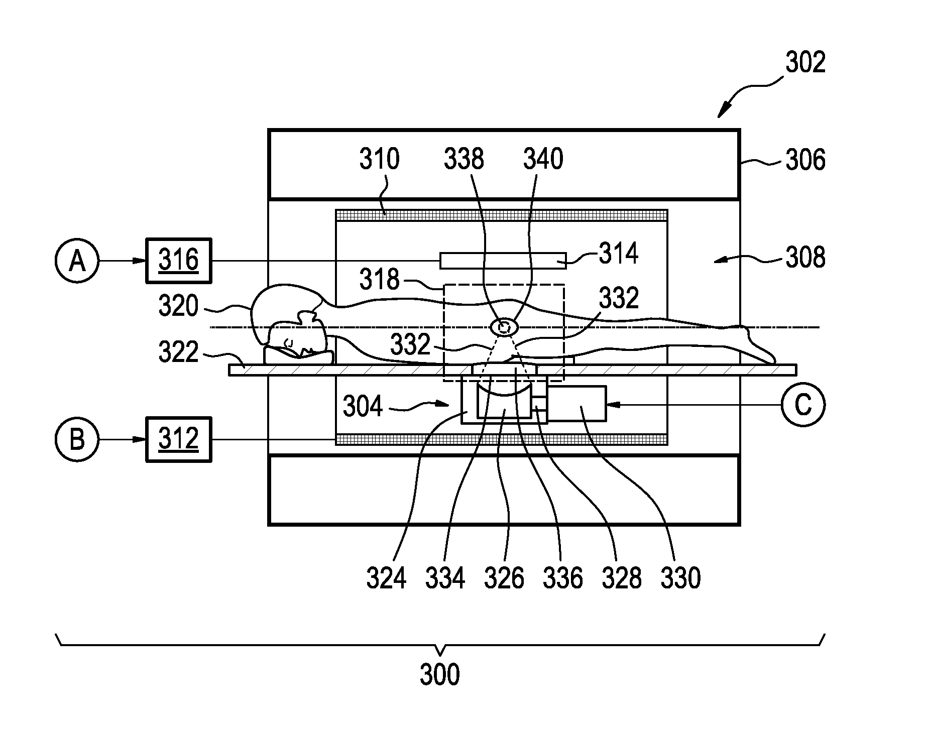
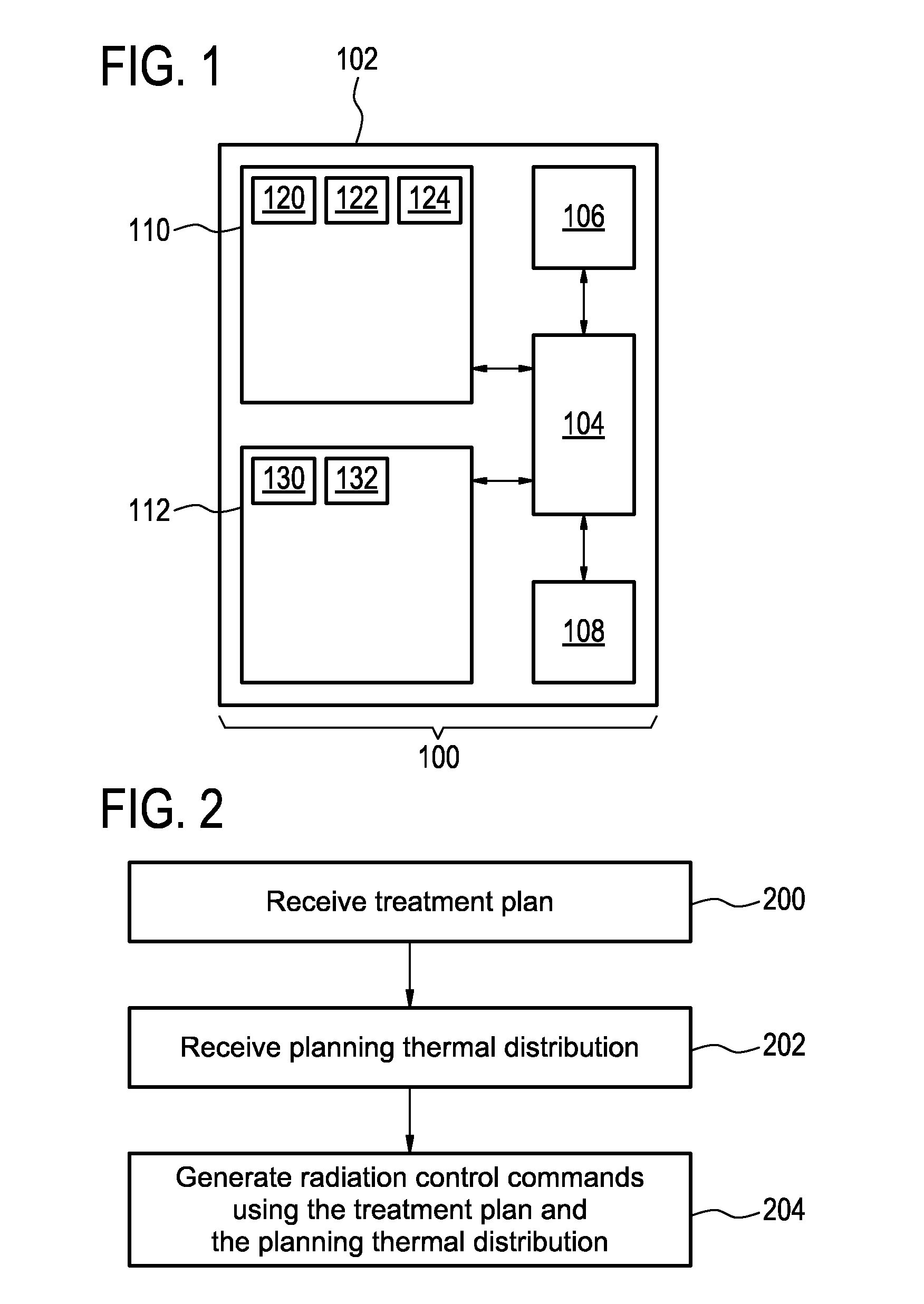
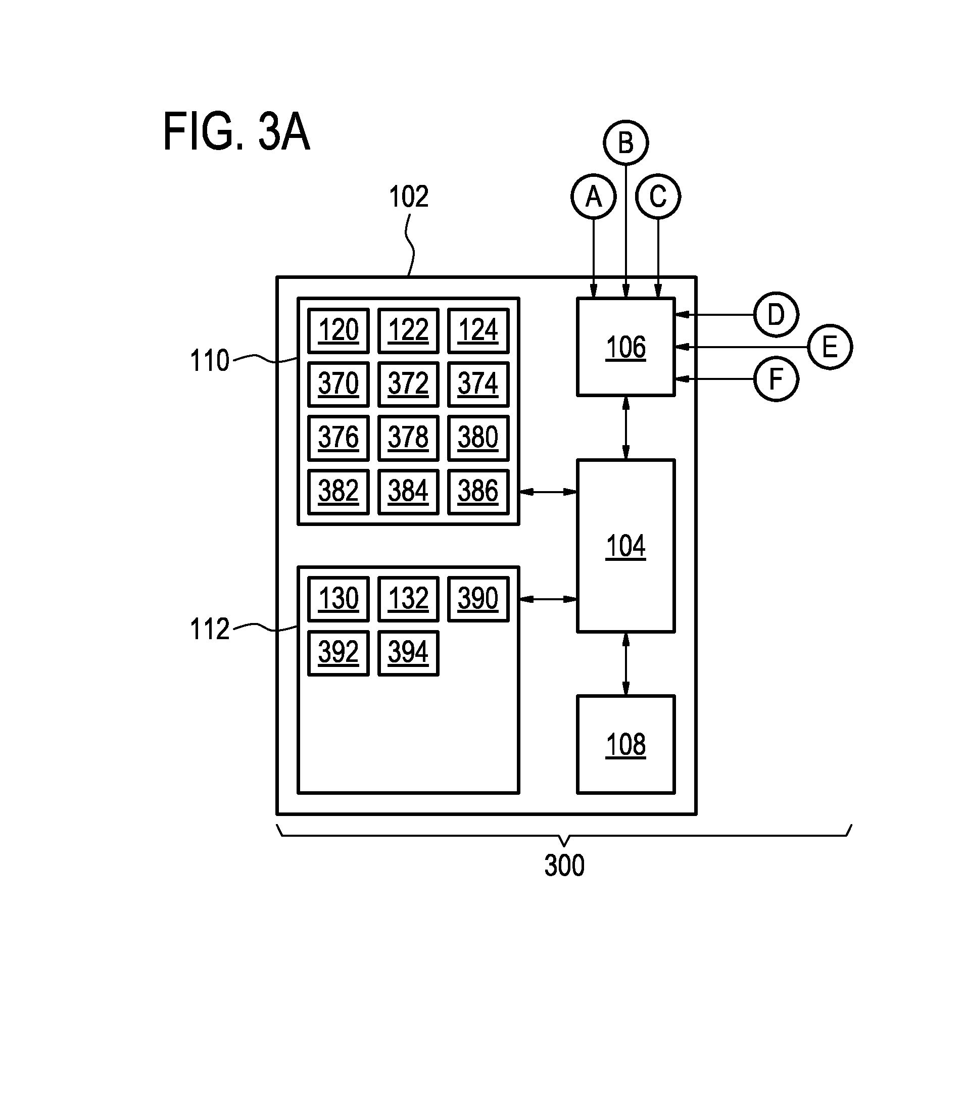
[0070]FIG. 1 shows an example of a medical apparatus 100. The medical apparatus is shown as comprising a computer 102. The computer 102 has a processor 104. The processor 104 is connected to a hardware interface 106. The hardware interface may enable the processor 104 to control other components of the medical apparatus 100. For example in other examples the medical apparatus 100 may comprise other components such as a high-intensity focused ultrasound system or even a radiation therapy system. The processor 104 is shown as being connected also to an optional user interface 108. The processor 104 is also in communication or connected to computer storage 110 and computer memory 112. The contents of the computer storage 110 and the computer memory 112 may...


PUM


Abstract

The invention provides for a medical apparatus (100, 300, 400) comprising a processor (104). Execution instructions (120, 122, 124, 370, 372, 374, 376, 378, 380, 382, 384, 386) causes the processor to receive (200) a treatment plan (120) descriptive of an ionizing radiation beam treatment of a target zone (340) within a subject (320) using a radiation beam therapy system (301) with a radiation source (354) and a gantry (350). The radiation source is operable for aiming a radiation beam path (358) at a rotational axis (352) of the gantry. The instructions further cause the processor to receive (202) a planning thermal distribution (122) descriptive of ultrasound heating of the subject with a high intensity focused ultrasound system (304) of a heating zone (338) and an ultrasound beam path (332) within the subject. The target zone is within the heating zone. The instructions further cause the processor to generate (204) radiation control command data (124) using the planning thermal distribution and the treatment plan. The radiation control command data is executable to cause the radiation source to reduce irradiation of the target zone when more than a predetermined volume of the radiation beam path intersects the ultrasound beam path.

Description

TECHNICAL FIELD[0001]The invention relates to radiation beam therapy, in particular to radiation beam therapy combined with hyperthermia.BACKGROUND OF THE INVENTION[0002]Mild hyperthermia (HT) is a therapeutic technique in which tissue is heated to temperatures (e.g., 38-45° C.) above body temperature, but below ablative temperatures. These hyperthermia treatments may result in physiological (e.g., perfusion) and cellular (e.g., gene expression) changes that improve the therapeutic effectiveness when used in conjunction with chemotherapy or radiation therapy. HT induces a multitude of changes, which provide clinical benefits that make it synergistic with many chemotherapeutic agents and radiation therapy. In addition to physiological and cellular changes, hyperthermia may be used with temperature responsive or non-responsive drug delivery systems to reduce toxicity and improve overall efficacy.[0003]There are a number of currently available devices that can heat target tissue to the...

Claims


Application Information

Patent Timeline
Patent Type & Authority Applications(United States)
IPC IPC(8): A61N7/02A61B5/055A61N5/10
CPCA61N7/02A61N5/1081A61N2005/1087A61N5/1039A61B5/055A61B34/10A61B2017/00084A61B2034/101A61B2034/105A61B2090/374A61N5/1064A61N5/1067G01R33/4804G01R33/4814
Inventor MOUGENOT, CHARLES
Owner KONINKLJIJKE PHILIPS NV
Why Eureka
Try Eureka