Rotary tool and method for manufacturing

a technology of rotary tools and manufacturing methods, applied in the field of rotary tools, can solve the problems of high mechanical load of drilling tools and high degree of wear, and achieve the effect of improving wear characteristics and improving properties

Active Publication Date: 2016-09-15
KENNAMETAL INC
View PDF7 Cites 12 Cited by
  • Summary
  • Abstract
  • Description
  • Claims
  • Application Information

AI Technical Summary

Benefits of technology

[0007]Embodiments of the present invention solve the problem of specifying a rotary tool, in particular a drilling tool, with improved properties, in particular with one or more improved wear characteristics.

Problems solved by technology

This embodiment is based on the consideration that, upon machining, large friction forces occur in the region of the first free surface segment immediately adjoining the major cutting edge, the large friction forces potentially leading to a high degree of wear, and overall to a high mechanical loading of the drilling tool.

Method used


Image

  • Rotary tool and method for manufacturing
  • Rotary tool and method for manufacturing

Examples


Embodiment Construction

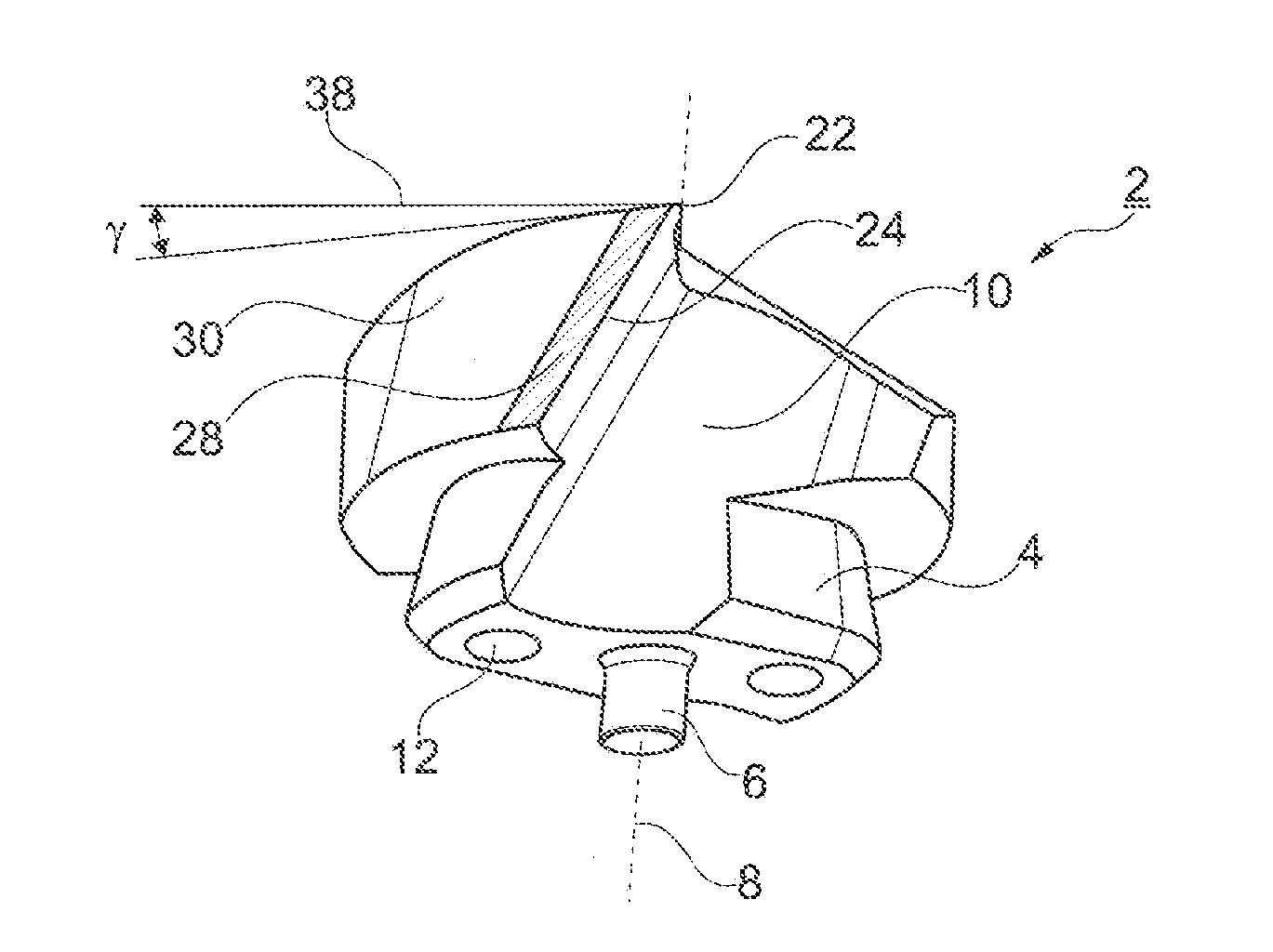
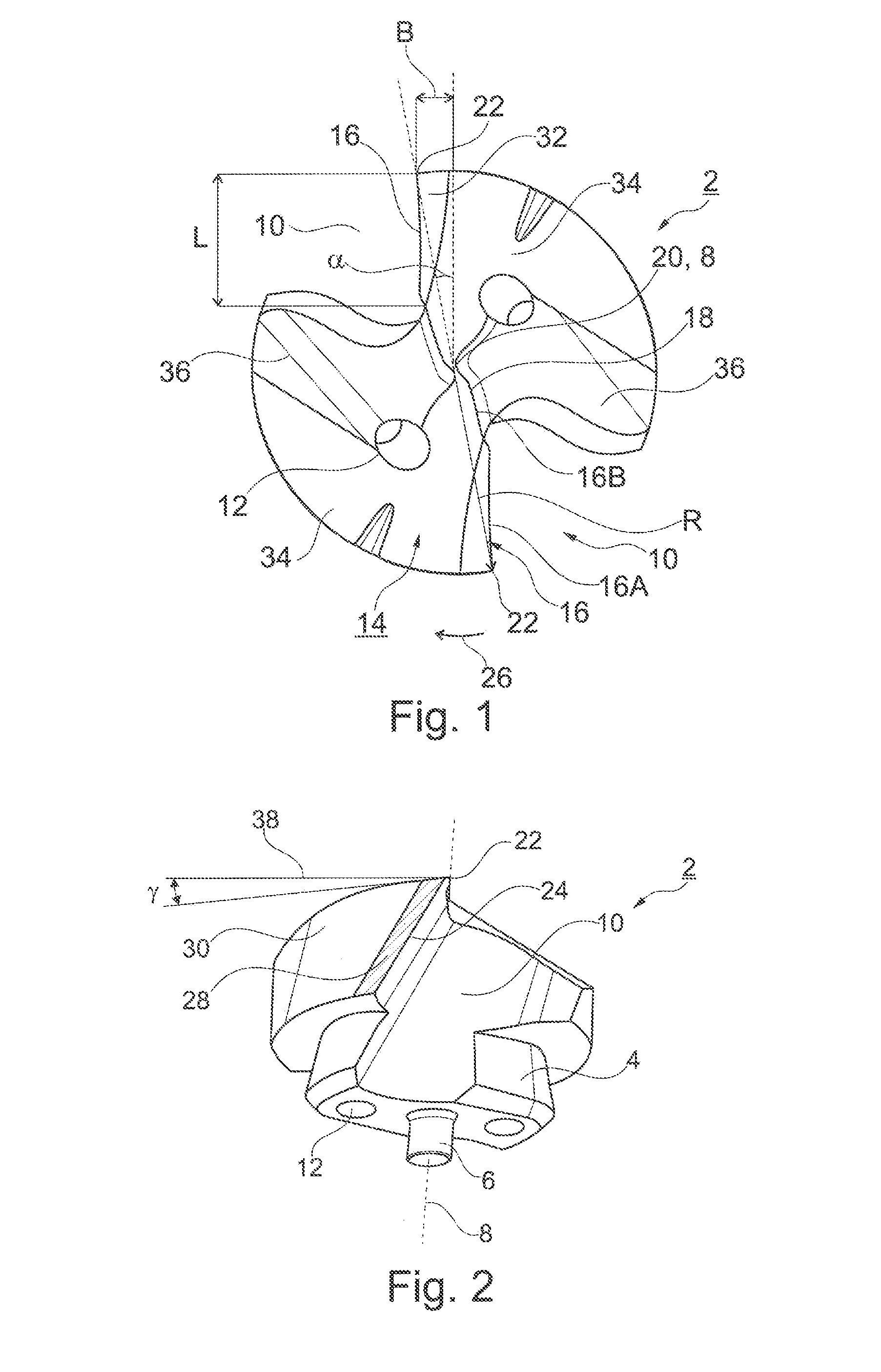
[0021]An exchangeable drill bit 2 is depicted here as an example in FIGS. 1 and 2, where said drill bit 2 can be inserted, in a manner not shown in detail, into a fluted base body to form a modular drilling tool. For this purpose the drill bit 2 comprises an attachment peg 4 with which it can be inserted into a corresponding receptacle of the base body where it can clamped and reversibly interchanged. A clamping attachment as well as a torque transfer take place via the attachment peg 4. An insertion peg 6 adjoins the attachment peg 4.

[0022]The drill bit 2 extends along a longitudinal axis 8 which simultaneously defines a rotation axis around which the drill bit 2 rotates during the operation. The drill bit 2 is designed with fluting and, in the exemplary embodiment, has two flutes 10 which are continued into the base body. Furthermore, in the exemplary embodiment coolant bores 12 are fashioned which penetrate the drill bit 2 in the longitudinal direction and exit at a front-facing ...


PUM

PropertyMeasurementUnit
angleaaaaaaaaaa
clearance angleaaaaaaaaaa

Abstract

A rotary tool, in particular drilling tool, extends along a longitudinal axis and has an end surface; a brad point; and at least one major cutting edge extending outward up to an edge corner. A first free surface segment adjoins the major cutting edge, and a second free surface segment in turn adjoins said first free surface segment. To keep the stress, in particular the wear, low in the region of the end surface, the first free surface segment has a lower average abrasiveness than the second free surface segment.

Description

BACKGROUND[0001]1. Field of the Invention[0002]The present invention relates to a rotary tool, and more particularly to a drilling tool, which extends along a longitudinal axis and has a front end surface with a brad point, with a first major cutting edge extending outward up to an outer edge corner; and with a first free surface segment adjoining the major cutting edge; and with a second free surface segment adjoining said first free surface segment. The present invention also relates to a method of making a rotary tool.[0003]2. Background Information[0004]A rotary tool upon which embodiments of the present invention improves is disclosed in U.S. Pat. No. 4,759,667, for example. Furthermore, a drilling tool having what is known as a four-surface ground section is also disclosed in U.S. Pat. No. 4,983,079.[0005]The end surface of such drills having a multi-surface ground section typically has a first free surface segment adjoining the respective major cutting edge in the direction o...

Claims


Application Information

Patent Timeline
Patent Type & Authority Applications(United States)
IPC IPC(8): B23B51/02B24B3/26
CPCB23B51/02B23B2251/18B23B2251/04B24B3/26B23B2251/02B23B2251/14B23B2228/12Y10T408/906
Inventor SCHWAEGERL, JUERGENKAUPER, HERBERT RUDOLF
Owner KENNAMETAL INC
Why Eureka
Try Eureka