Method for manufacturing a stage of a steam turbine

Active Publication Date: 2016-09-15
NUOVO PIGNONE TECH SRL
View PDF2 Cites 4 Cited by
  • Summary
  • Abstract
  • Description
  • Claims
  • Application Information

AI Technical Summary

Benefits of technology

[0006]A disadvantage of the above described prior art is in the welding phase of the above described method. Indeed, this step has to

Problems solved by technology

A disadvantage of the above described prior art is in the welding phase of the above des

Method used


Image

  • Method for manufacturing a stage of a steam turbine
  • Method for manufacturing a stage of a steam turbine
  • Method for manufacturing a stage of a steam turbine

Examples


Embodiment Construction

[0017]The following description of exemplary embodiments refer to the accompanying drawings. The same reference numbers in different drawings identify the same or similar elements. The following detailed description does not limit the invention. Instead, the scope of the invention is defined by the appended claims.

[0018]Reference throughout the specification to “one embodiment” or “an embodiment” means that a particular feature, structure, or characteristic described in connection with an embodiment is included in at least one embodiment of the subject matter disclosed. Thus, the appearance of the phrases “in one embodiment” or “in an embodiment” in various places throughout the specification is not necessarily referring to the same embodiment. Further, the particular features, structures or characteristics may be combined in any suitable manner in one or more embodiments.

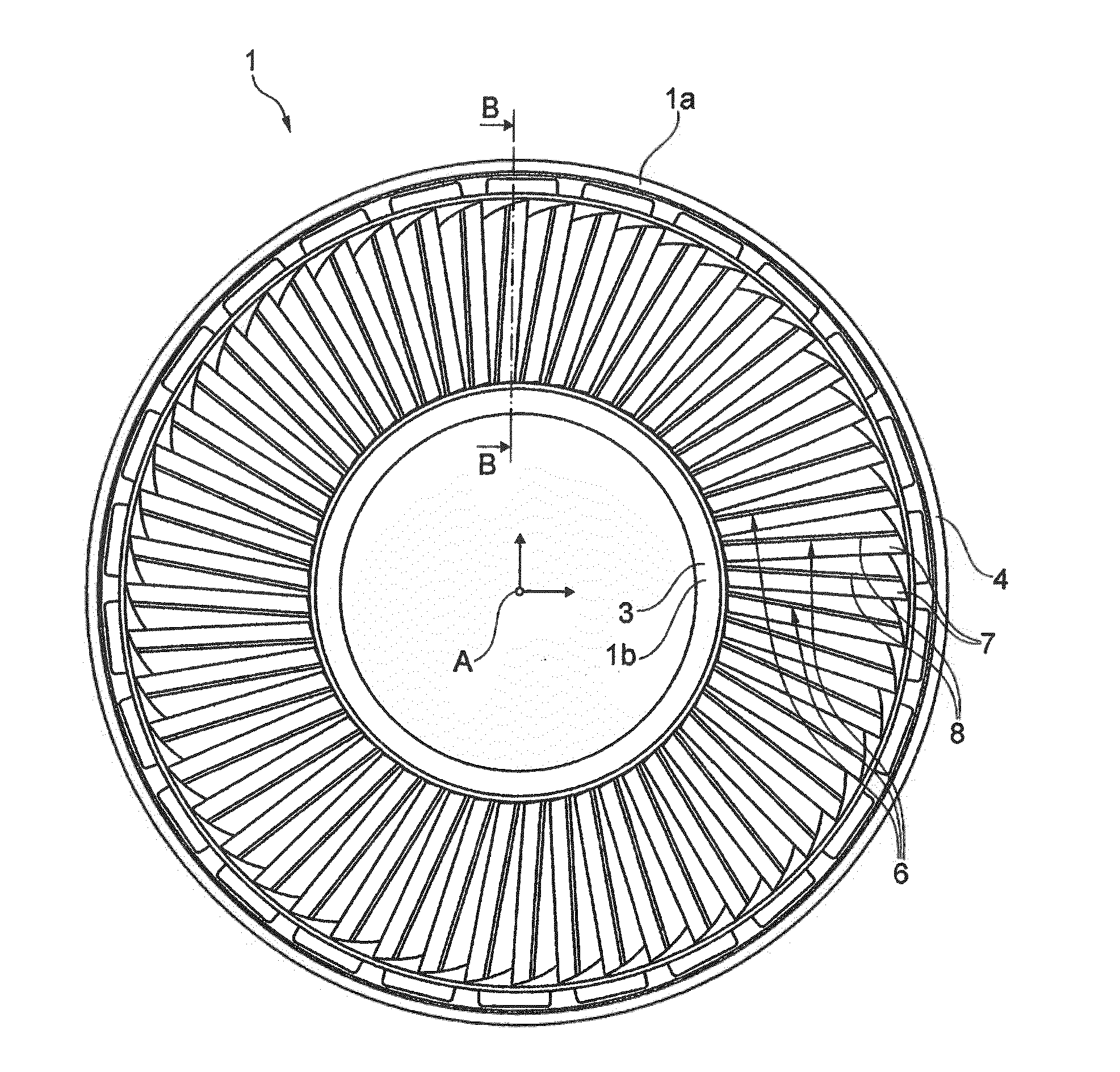
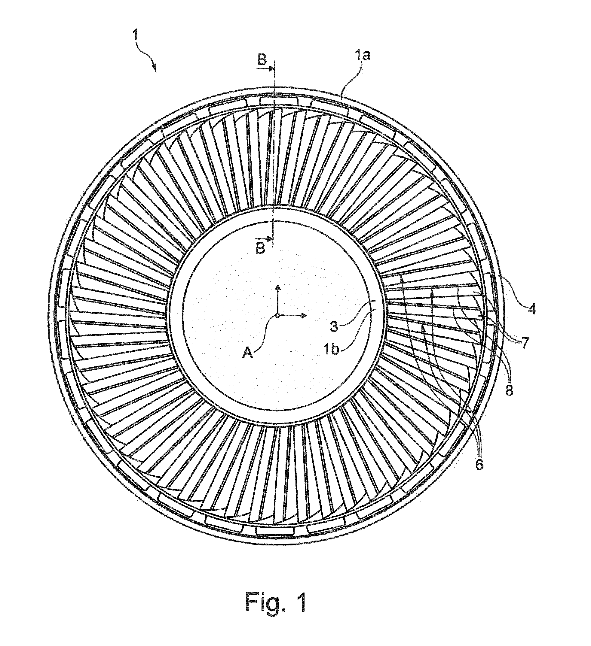
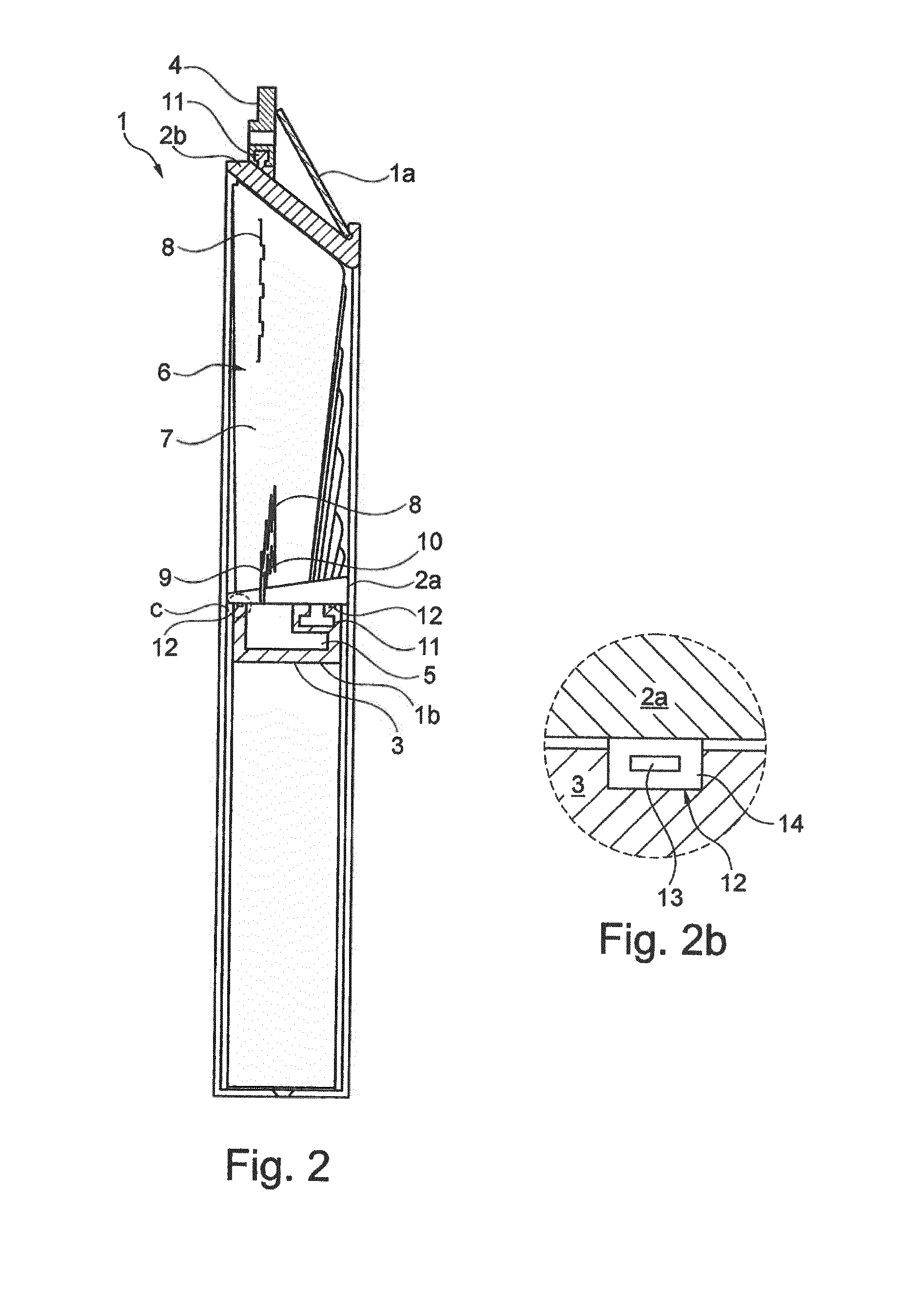
[0019]Therefore, a stage of a steam turbine will be described by referring to the attached figures, in which wil...


PUM


Abstract

A method for manufacturing a stage of a steam turbine comprising the steps of milling a block of material to define a sector having a plurality of blades, each blade having an external surface; machining an opening in the external surface of at least one of the blades; machining a cavity in fluid communication with the opening; the step of machining the cavity being performed by wire electric discharge machining.

Description

BACKGROUND[0001]Embodiments of the present invention relate to a method for manufacturing a stage of a steam turbine. Specifically, the method relates to the manufacturing of a stage having hollow blades.[0002]In steam turbines, partial condensation of the steam occurs at their last stage or stages. In particular, condensation occurs on the airfoil portion of the stator blades of a so-called “condensing stage”, typically the last stage of the turbine. If droplets are generated as a consequence of condensation, they leave the static stator blades and they hit the rotating rotor blades; therefore, damages to the rotor blades may occur. In order to reduce the damages caused by the droplets, the rotation speed of the rotor blades may be reduced. However, in this way the efficiency of the turbine is also reduced.[0003]Alternatively, in order to reduce any damage on the rotor blades, solutions exist for collecting the condensation before the generation of droplets. The most typical of the...

Claims


Application Information

Patent Timeline
IPC IPC(8): F01D5/30B23H9/14F01D11/00B23C3/18F01D5/02F01D5/12
CPCF01D5/3069F01D5/021F01D5/12F01D11/006B23C3/18B23C2215/44F05D2220/31F05D2230/12F05D2300/10F05D2300/431B23H9/14F01D5/14F01D5/147F01D5/3038F01D11/008F01D25/32F05D2230/51F05D2230/53F05D2230/10
Inventor BENCINI, GIACOMOGRILLI, MARCOCOSI, LORENZO
Owner NUOVO PIGNONE TECH SRL
Why Eureka
Try Eureka