Methods and systems for detector gap corrections

a detector and gap correction technology, applied in the field of non-invasive diagnostic imaging, can solve the problems of corresponding gaps between some image slices, affecting the accuracy of image reconstruction, so as to achieve the effect of reducing position errors

Active Publication Date: 2016-09-15
GENERAL ELECTRIC CO
View PDF1 Cites 3 Cited by
  • Summary
  • Abstract
  • Description
  • Claims
  • Application Information

AI Technical Summary

Benefits of technology

The patent describes a method for reducing positional errors in an image without needing to fully reconstruct the detector geometry or modify it. This is achieved by generating a sinogram based on photon coincidence events and selectively inserting one or more pseudo-slices into it. The result is an image that is more accurate and reliable.

Problems solved by technology

However, each of the detector blocks may be separated by a small gap, which in turn results in a corresponding gap between some of the image slices.
If image reconstruction does not account for these gaps, positioning errors arising from these gaps may propagate through the image reconstruction and subsequent image stitching processes.
Assuming the CT imaging perfectly images the body of a patient without positioning errors, substantial mis-registration errors may occur when stitching the CT image and the PET image together.
That is, objects in the final PET / CT image may be incorrectly positioned within the image.
However, eliminating the gaps would require a substantial redesign of the imaging system itself.
However, current methods for image reconstruction utilize symmetries of the detector geometry.
Accounting for the gap breaks at least some of the symmetries, and as a result substantially slows down the reconstruction time.

Method used


Image

  • Methods and systems for detector gap corrections
  • Methods and systems for detector gap corrections
  • Methods and systems for detector gap corrections

Examples


Embodiment Construction

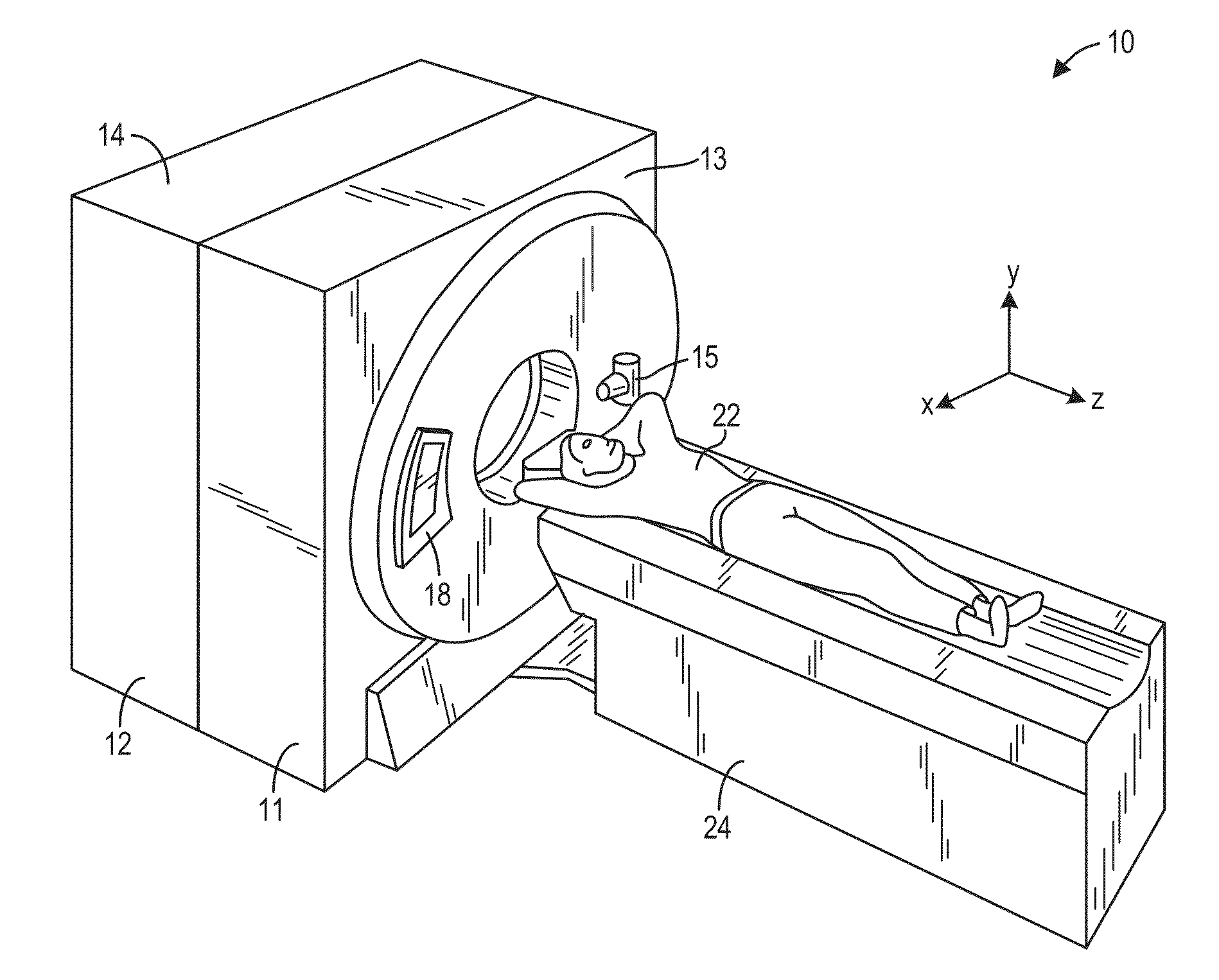
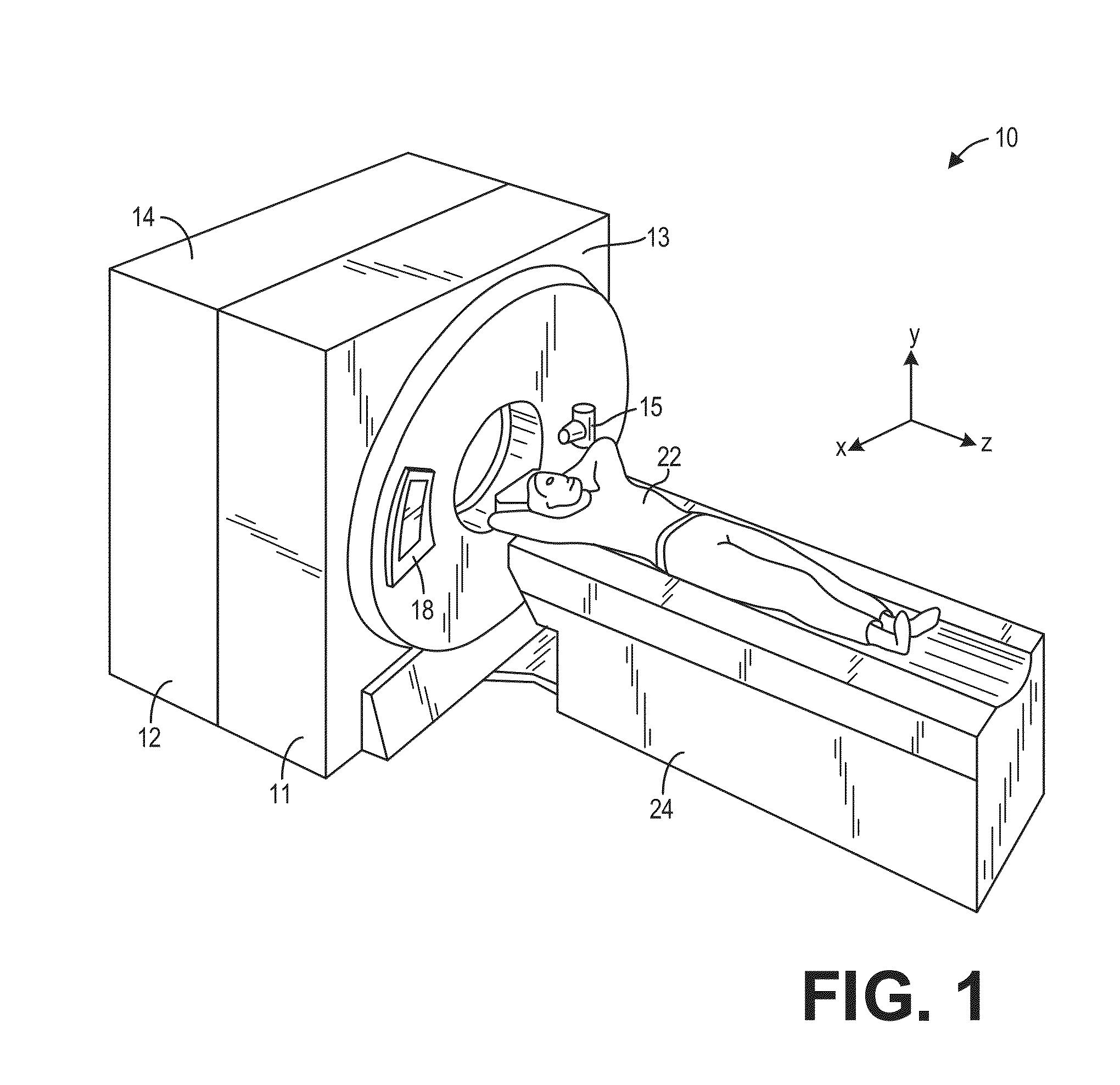
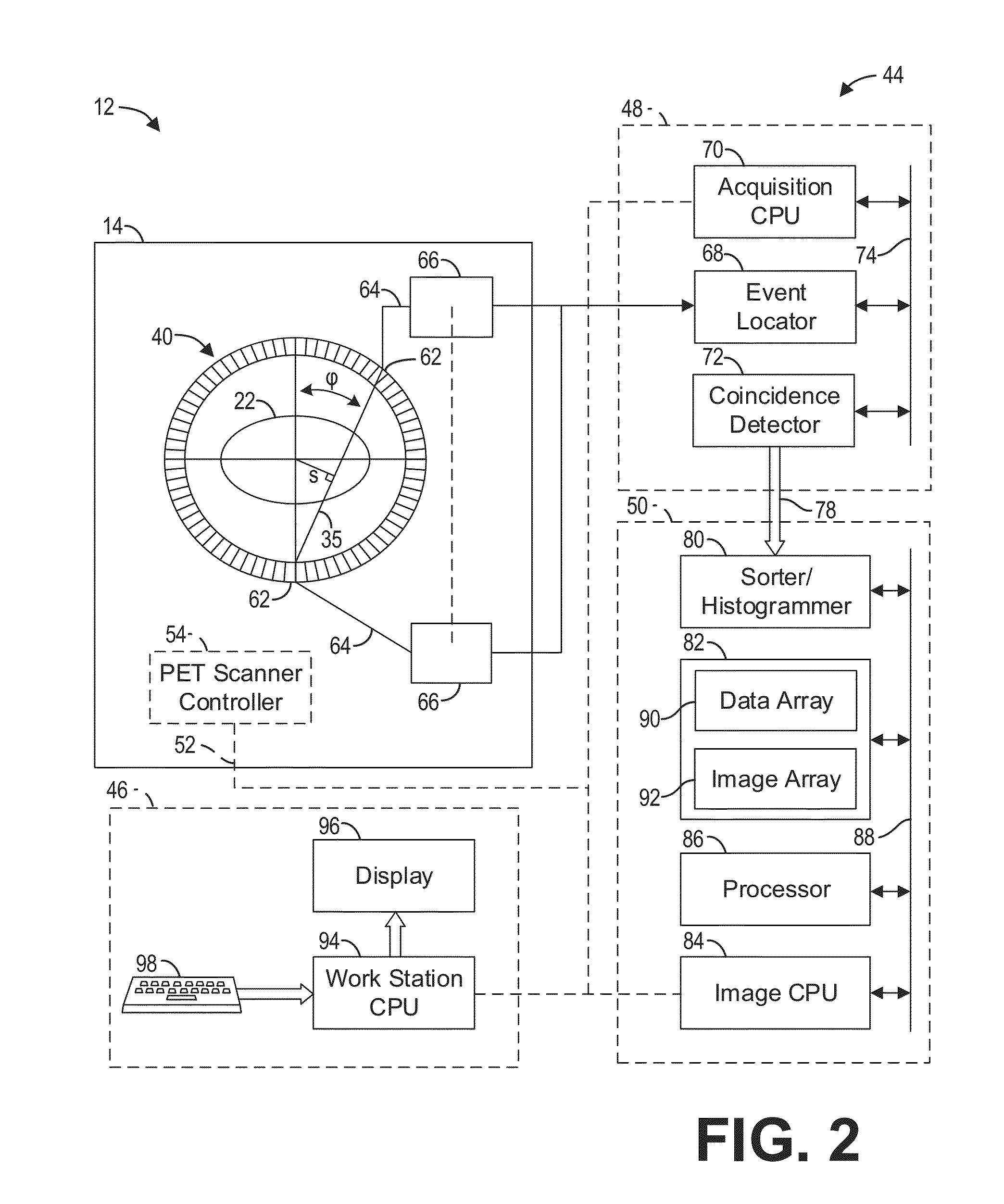
[0017]The following description relates to various embodiments of medical imaging systems. In particular, methods and systems are provided for correcting positional errors arising from gaps in a detector assembly. An example of a positron emission tomography (PET) imaging system that may be used to acquire images processed in accordance with the present techniques is provided in FIGS. 1 and 2. As depicted in FIG. 3, the positions of the detectors in the axial direction may not be uniformly spaced. For example, gaps may be present between detector blocks. These gaps cause shifts in the positions of the reconstructed images unless accounted for by the reconstruction algorithm, as depicted in FIG. 4. A method for compensating for the gaps includes inserting pseudo-slices into gaps within a sinogram, as depicted in FIG. 5. In some examples, the sinogram may be transformed from a first data structure, such as the data structure illustrated in FIG. 6, into a second data structure, such as...


PUM


Abstract

Methods and systems are provided for correcting positional errors in an image arising from gaps in a detector assembly. In one embodiment, a method comprises generating a sinogram based on a plurality of photon coincidence events, selectively inserting one or more pseudo-slices into the sinogram, and generating an image based on the sinogram including the one or more pseudo-slices. In this way, positional errors may be reduced without modifying an image reconstruction algorithm to include a full detector geometry or modifying the detector geometry itself.

Description

FIELD[0001]Embodiments of the subject matter disclosed herein relate to non-invasive diagnostic imaging, and more particularly, to image reconstruction using Positron Emission Tomography (PET).BACKGROUND[0002]PET generates images that represent the distribution of positron-emitting nuclides within the body of a patient. When a positron interacts with an electron by annihilation, the entire mass of a positron-electron pair is converted into two 511-keV photons. The photons are emitted in opposite directions along a line of response (LOR). The annihilation photons are detected by detectors that are placed on both sides of the line of response, in a configuration such as a detector ring. Coincidence occurs when these photons arrive and are detected at the detector elements at the same time. An image is then generated based on the acquired image data that includes the annihilation photon detection information.[0003]Modern PET scanners include a plurality of detector rings coaxially arra...

Claims


Application Information

Patent Timeline
IPC IPC(8): G06T11/00G01T1/29G06T7/00G01T1/202
CPCG06T11/003G01T1/202G01T1/2985G06T2207/10081G06T7/0081G06T2207/10104G06T7/0012G01T1/1647G06T11/006
Inventor MATTHEWS, CHRISTOPHER GERALD
Owner GENERAL ELECTRIC CO
Why Eureka
Try Eureka