Carbon nanotube-based ternary comparator

a technology of carbon nanotubes and ternary comparators, applied in the field of ternary comparators, can solve the problems of complex interconnections, low operation speed, and limited information carrying capacity of conventional binary logic systems, and achieve the effect of small area and low power consumption

Active Publication Date: 2016-09-15
NINGBO UNIV
View PDF0 Cites 1 Cited by
  • Summary
  • Abstract
  • Description
  • Claims
  • Application Information

AI Technical Summary

Benefits of technology

[0021]The carbon nanotube-based ternary comparator of the invention adopts the CNFETs to design the comparison circuit. The comparison circuit comprises the first comparison unit for producing the greater-than-or-equal-to signal and the second comparison unit for producing the less-than-or-equal-to signal. The first two-bit ternary signal is converted into the first three-bit binary signal and the phase inverted signal of the first three-bit binary signal by the first decoder. The second two-bit ternary signal is converted into the second three-bit binary signal and the phase inverted signal of the fir...

Problems solved by technology

The conventional binary logic system has limited information c...

Method used


Image

  • Carbon nanotube-based ternary comparator
  • Carbon nanotube-based ternary comparator
  • Carbon nanotube-based ternary comparator

Examples


example 1

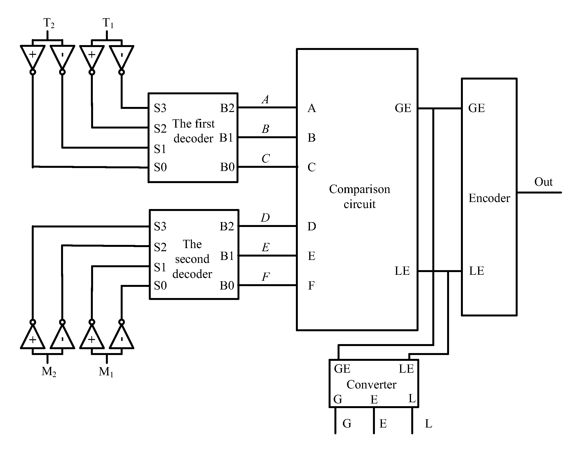
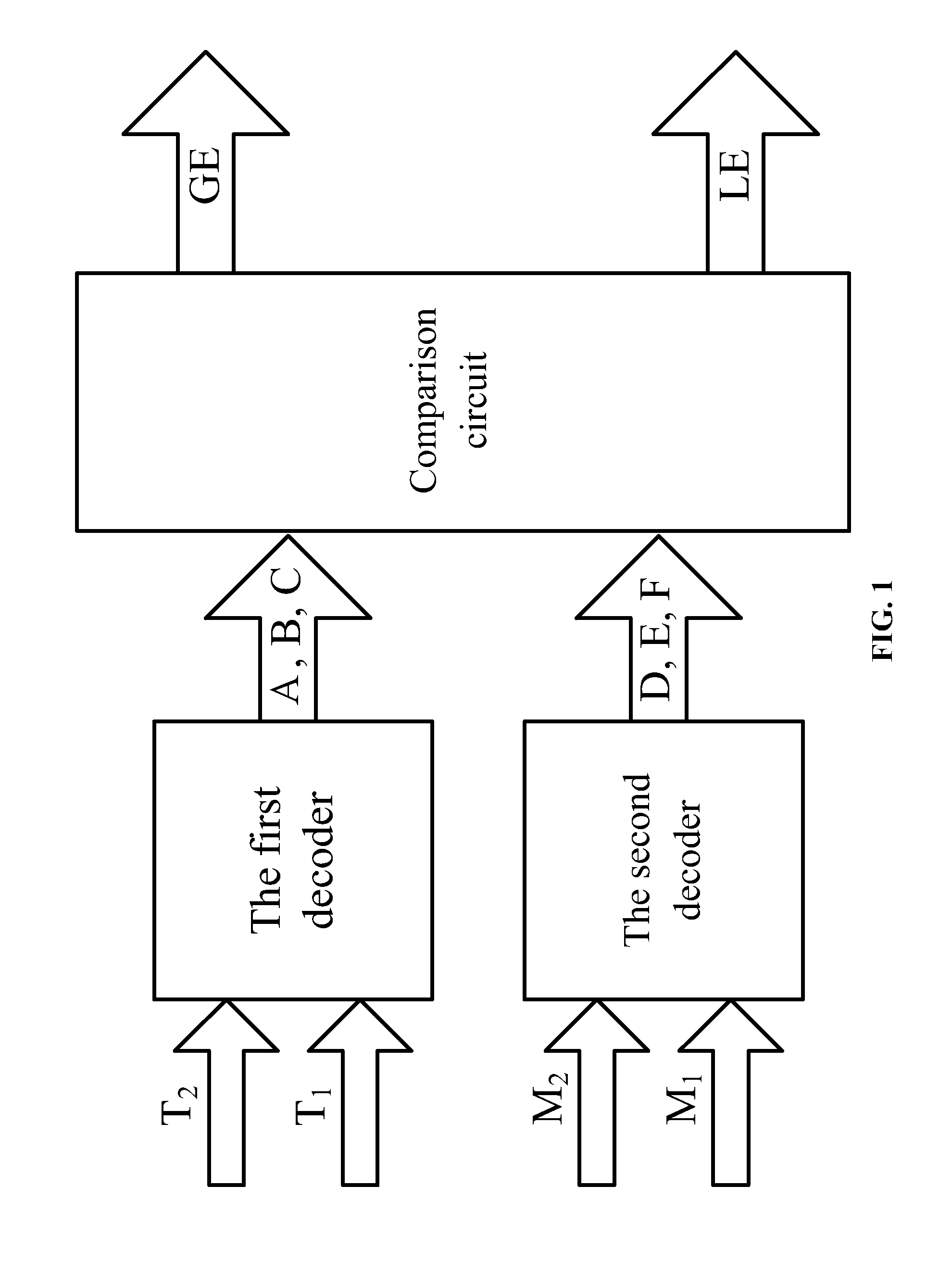
[0034]As shown in FIG. 1, a carbon nanotube-based ternary comparator comprises: a first decoder, a second decoder, and a comparison circuit. A first two-bit ternary signal T2 T1 is input into a signal input terminal of the first decoder. A first three-bit binary signal ABC and a phase inverted signal ABC of the first three-bit binary signal ABC are output from a signal output terminal of the first decoder. A second two-bit ternary signal M2 M1 is input into a signal input terminal of the second decoder. A second three-bit binary signal DEF and a phase inverted signal DEF of the second three-bit binary signal are output from a signal output terminal of the second decoder. The comparison circuit comprises: a first comparison unit for producing a greater-than-or-equal-to GE signal and a second comparison unit for producing a less-than-or-equal-to signal LE.

[0035]As shown in FIG. 3, the first comparison unit comprises: a first CNFET T1, a second CNFET T2, a third CNFET T3, a fourth CNFE...

example 2

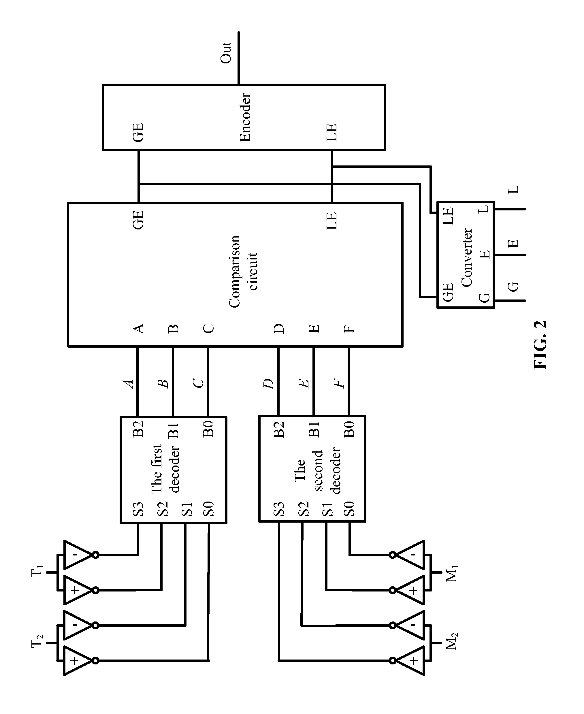
[0042]As shown in FIG. 2, a carbon nanotube-based ternary comparator, comprises: a first decoder, a second decoder, and a comparison circuit. A first two-bit ternary signal T2 T1 is input into a signal input terminal of the first decoder. A first three-bit binary signal ABC and a phase inverted signal ABC of the first three-bit binary signal ABC are output from a signal output terminal of the first decoder. A second two-bit ternary signal M2 M1 is input into a signal input terminal of the second decoder. A second three-bit binary signal DEF and a phase inverted signal DEF of the second three-bit binary signal are output from a signal output terminal of the second decoder. The comparison circuit comprises: a first comparison unit for producing a greater-than-or-equal-to signal GE and a second comparison unit for producing a less-than-or-equal-to signal LE.

[0043]As illustrated in FIG. 3, a circuit structure of the first comparison unit is the same as that in Example 1. As illustrated ...


PUM


Abstract

A carbon nanotube-based ternary comparator including a first decoder, a second decoder, and a comparison circuit. The comparison circuit includes: a first comparison unit for producing a greater-than-or-equal-to signal, and a second comparison unit for producing a less-than-or-equal-to signal. A first two-bit ternary signal is input into the signal input terminal of the first decoder. A first three-bit binary signal and a phase inverted signal of the first three-bit binary signal are output from a signal output terminal of the first decoder. A second two-bit ternary signal is input into the signal input terminal of the second decoder. A second three-bit binary signal and a phase inverted signal of the second three-bit binary signal are output from the signal output terminal of the second decoder.

Description

CROSS-REFERENCE TO RELATED APPLICATIONS[0001]Pursuant to 35 U.S.C. §119 and the Paris Convention Treaty, this application claims the benefit of Chinese Patent Application No. 201510106089.4 filed Mar. 11, 2015, the contents of which are incorporated herein by reference. Inquiries from the public to applicants or assignees concerning this document or the related applications should be directed to: Matthias Scholl P. C., Attn.: Dr. Matthias Scholl Esq., 245 First Street, 18th Floor, Cambridge, Mass. 02142.BACKGROUND OF THE INVENTION[0002]1. Field of the Invention[0003]The invention relates to a ternary comparator, and more particularly to a carbon nanotube-based ternary comparator.[0004]2. Description of the Related Art[0005]Comparator is a key element of functional circuits. The conventional binary logic system has limited information carrying capacity, low operation speed, and complex interconnections.[0006]Carbon nanotube field effect transistor (CNFET) is a new type of element hav...

Claims


Application Information

Patent Timeline
IPC IPC(8): H01L51/00H03K5/24
CPCH01L51/0048H03K5/22H03K5/2472H10K85/221
Inventor WANG, PENGJUNTANG, WEITONGWANG, QIAN
Owner NINGBO UNIV
Why Eureka
Try Eureka