Directional coupler and wireless communication device

a wireless communication device and directional coupler technology, applied in the direction of coupling devices, electrical devices, transmission, etc., can solve the problems of not always easy to simultaneously satisfy the required characteristics of coupling and isolation, and achieve the effect of suppressing insertion loss, long time, and reducing the size of the coupler

Active Publication Date: 2016-09-15
TDK CORPARATION
View PDF8 Cites 4 Cited by
  • Summary
  • Abstract
  • Description
  • Claims
  • Application Information

AI Technical Summary

Benefits of technology

[0021]The invention described in the foregoing Patent Document 1 (JP-A-2002-280810) is intended to solve a problem of exacerbated isolation due to insufficient self-inductance value of a main line and a sub-line (particularly, the sub-line) to the accompaniment of a reduction in size of a coupler. More specifically, the width of the sub-line is made relatively smaller than that of the main line, and the main line is made thicker than the sub-line in order to suppress an insertion loss. However, the invention described in this document is not capable of simultaneously adjusting the coupling and isolation. Also, w

Problems solved by technology

However, due to recent demands for a reduction in size and thickness and an increase in functionality of electronic components, and from the necessity of realizing a high pr

Method used


Image

  • Directional coupler and wireless communication device
  • Directional coupler and wireless communication device
  • Directional coupler and wireless communication device

Examples


Embodiment Construction

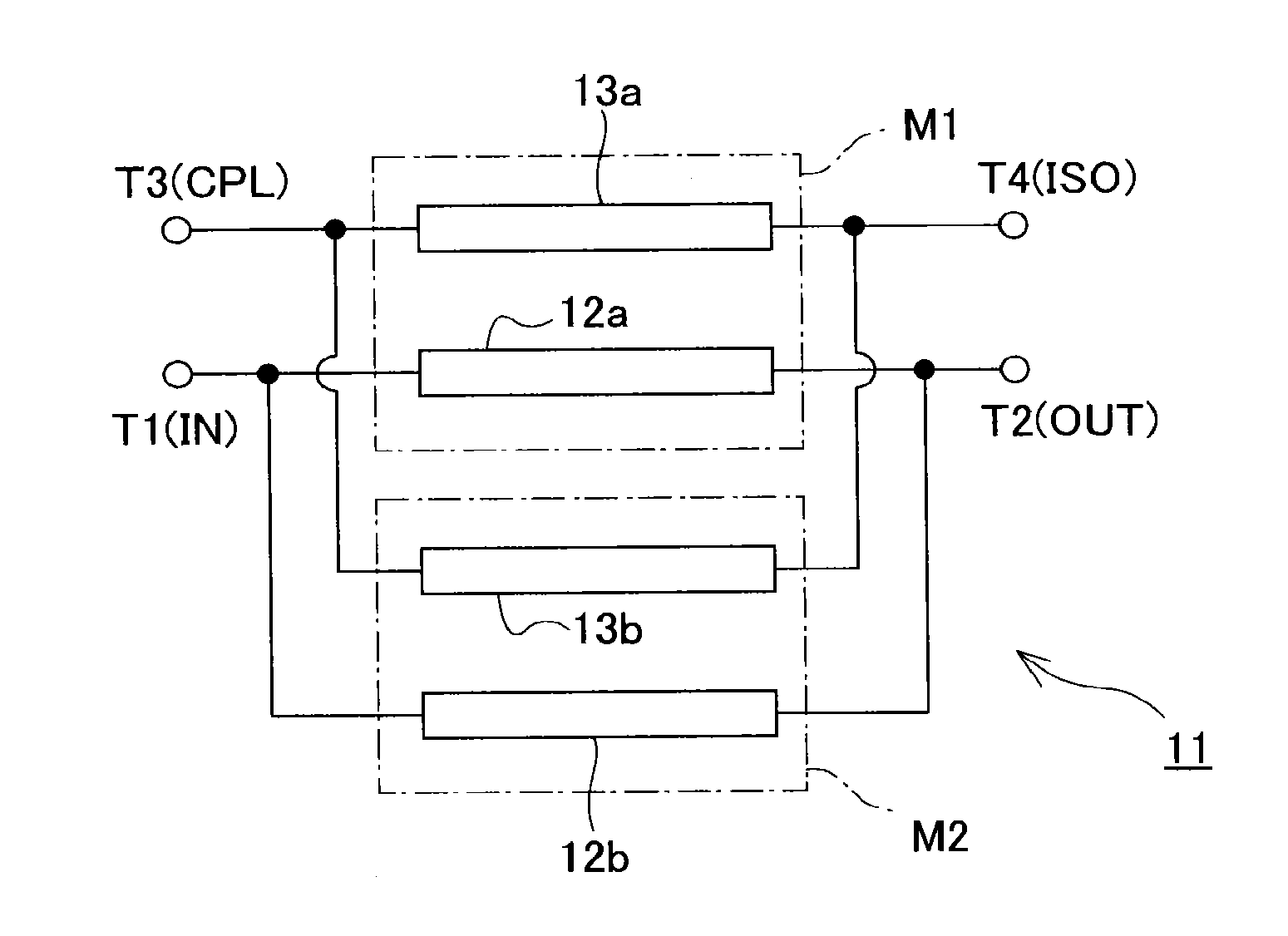
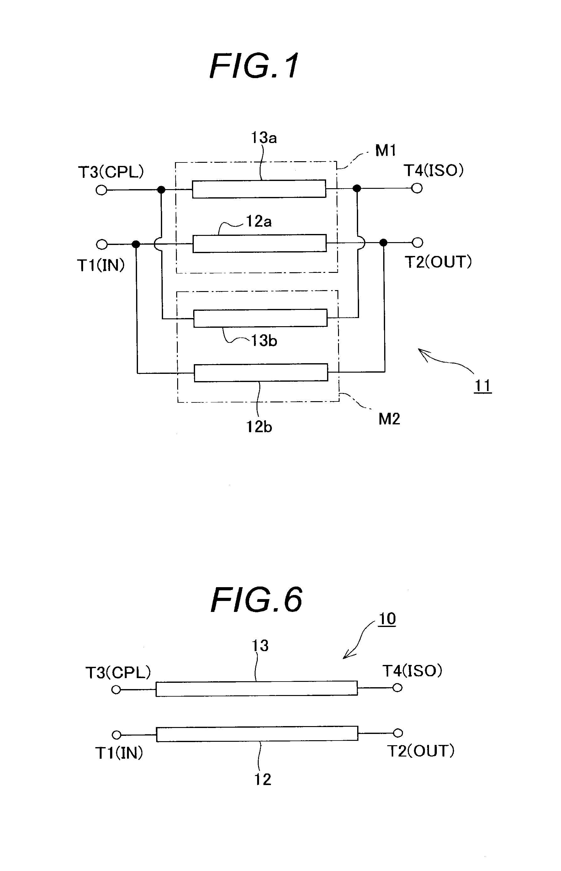
[0047]As illustrated in FIG. 1, a coupler 11 according to one embodiment of the present invention comprises a main line for transmitting a transmission signal, and a sub-line electromagnetically coupled to the main line, where the main line has a first main-line section 12a and a second main-line section 12b connected in parallel between an input terminal T1 and an output terminal T2, while the sub-line has a first sub-line section 13a and a second sub-line section 13b connected in parallel between a coupling terminal T3 and an isolation terminal T4. Also, the first main-line section 12a is disposed in close proximity to the first sub-line section 13a to cause them to electromagnetically couple to each other, while the second main-line section 12b is similarly disposed in close proximity to the second sub-line section 13b to cause them to electromagnetically couple to each other.

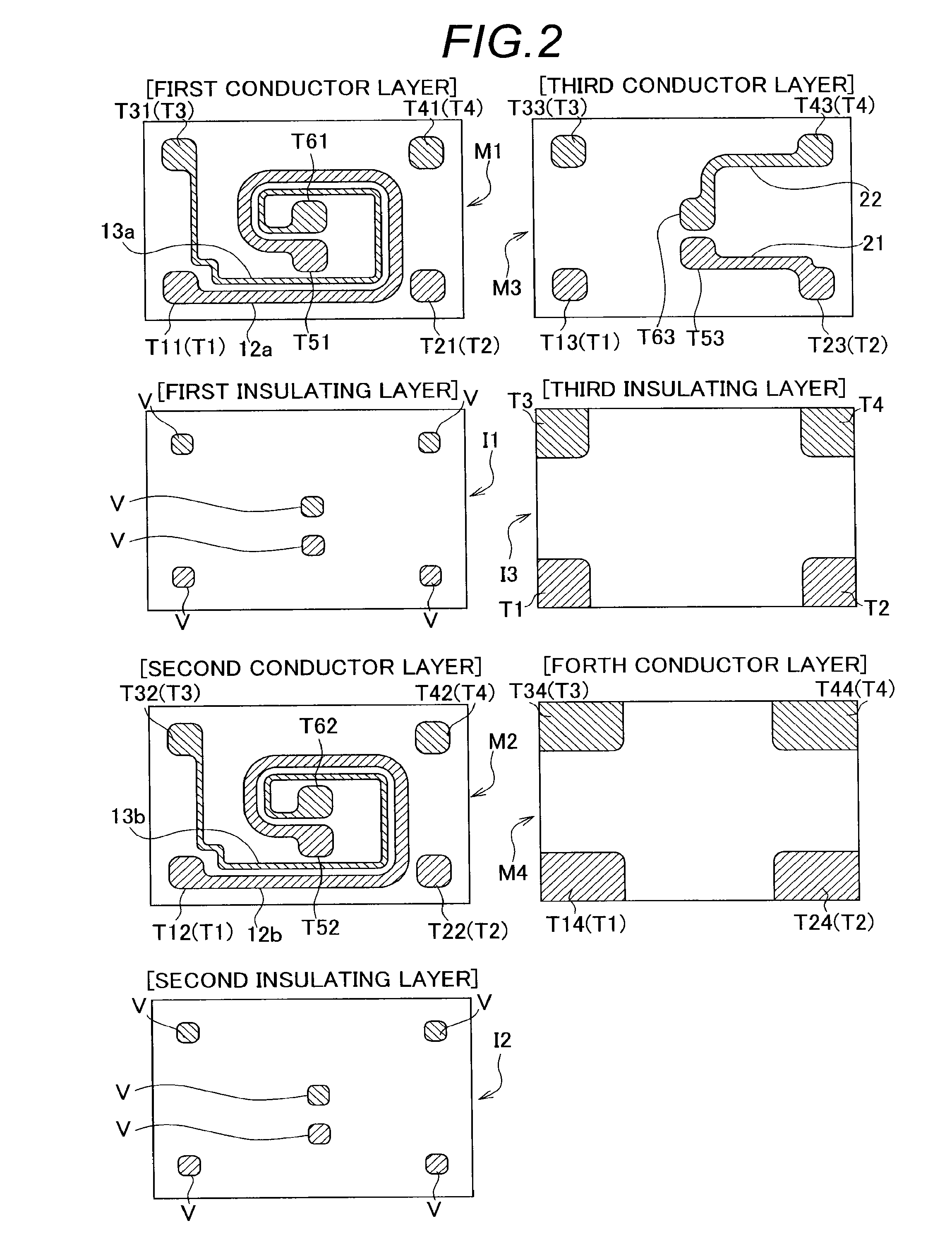
[0048]The main-line sections 12a, 12b and sub-line sections 13a, 13b, as well as terminals T1-T4 are arra...


PUM


Abstract

A directional coupler including a main line, a sub-line, an input terminal, an output terminal, a coupling terminal and an isolation terminal, wherein the main line includes a first main-line section formed on a first layer, and a second main-line section formed on a second layer; the first and the second main-line sections are connected in parallel between the input and the output terminals; the sub-line includes a first sub-line section formed on the first layer, and a second sub-line section formed on the second layer; the first and the second sub-line sections are connected in parallel between the coupling and the isolation terminals; the first main-line section and the first sub-line section are disposed in close proximity to each other to generate electromagnetic coupling; and the second main-line section and the second sub-line section are disposed in close proximity to each other to generate electromagnetic coupling.

Description

BACKGROUND OF THE INVENTION[0001]The present invention relates to a directional coupler and a wireless communication device, and particularly, to technologies for designing particular conductor patterns within a laminate which forms part of a directional coupler, thereby improving the characteristics of the directional coupler.[0002]A directional coupler (hereinafter sometimes referred to as the “coupler”) for extracting part of electric power propagated through a transmission line is an indispensable part for constructing a transmission circuit for a variety of wireless communication devices such as a mobile phone, a wireless LAN communication device, a communication device conforming to the Bluetooth (registered trademark) standard, and the like.[0003]Specifically, a coupler forms part of adjusting means for controlling a transmission signal to keep its level constant, and this adjusting means comprises a power amplifier (hereinafter sometimes referred to as the “PA”) capable of c...

Claims


Application Information

Patent Timeline
IPC IPC(8): H01P5/18H04B1/16H04B1/04
CPCH01P5/18H04B2001/0416H04B1/16H04B1/0475H04B1/40H01P5/184
Inventor MITAKE, YUKIO
Owner TDK CORPARATION
Why Eureka
Try Eureka