Method for generating load of wireless power receiver in wireless charging system and wireless power receiver

a wireless power receiver and wireless charging technology, applied in the field of wireless charging, can solve the problems of affecting the charging of batteries, limited applications, and failure detection of small objects, and achieve the effect of effective detection

Active Publication Date: 2016-09-15
SAMSUNG ELECTRONICS CO LTD
View PDF7 Cites 20 Cited by
  • Summary
  • Abstract
  • Description
  • Claims
  • Application Information

AI Technical Summary

Benefits of technology

[0021]Accordingly, an aspect of the present disclosure is to provide a PRU and a load generation method of the PRU, wherein a load is effectively detected by a PTU by adding a dummy load to the PRU when the PTU detects a load due to an impedance variation.

Problems solved by technology

However, these type of contacts, which normally project outward, may be easily contaminated by foreign bodies, which may inhibit the battery charging.
Currently, inductive charging is fairly common, but by its nature, has limited applications.
When sensing the placement by the PTU, too small a threshold for an impedance variation may result in faulty detection, and too large threshold may lead to detection failure for small objects.
Further, if an impedance difference between the PTU without the PRU placed thereon and the PTU with the PRU place thereon is not substantial, the PTU may not correctly sense a variation in the load.
Further, conventional detection methods have difficulty in detection because when the PRU is placed on the PTU, the resistance may vary but the variation in power due to the load variation may be too small to detect.
For example, when a load variation is caused at an alternating current (AC) terminal of the PRU, because different impedance variations are measured depending on combinations of the PTU and the PRU, if more load-pull power is consumed in the amplification unit of the PTU, the PTU may be subject to negative influences such as overcurrent or overvoltage.
Thus, if the value is not large, the PTU has difficulty in load detection, and if the value is too large, more standby power consumption may occur because more power should be transferred to a long beacon of the PTU.

Method used


Image

  • Method for generating load of wireless power receiver in wireless charging system and wireless power receiver
  • Method for generating load of wireless power receiver in wireless charging system and wireless power receiver
  • Method for generating load of wireless power receiver in wireless charging system and wireless power receiver

Examples


Embodiment Construction

[0051]Hereinafter, various embodiments of the present disclosure are described in detail with reference to the accompanying drawings. It should be noted that the same element names and numerals may be refer to the same or similar elements throughout the specification. Further, detailed descriptions of known functions or configurations are omitted to avoid obscuring the present disclosure in unnecessary detail.

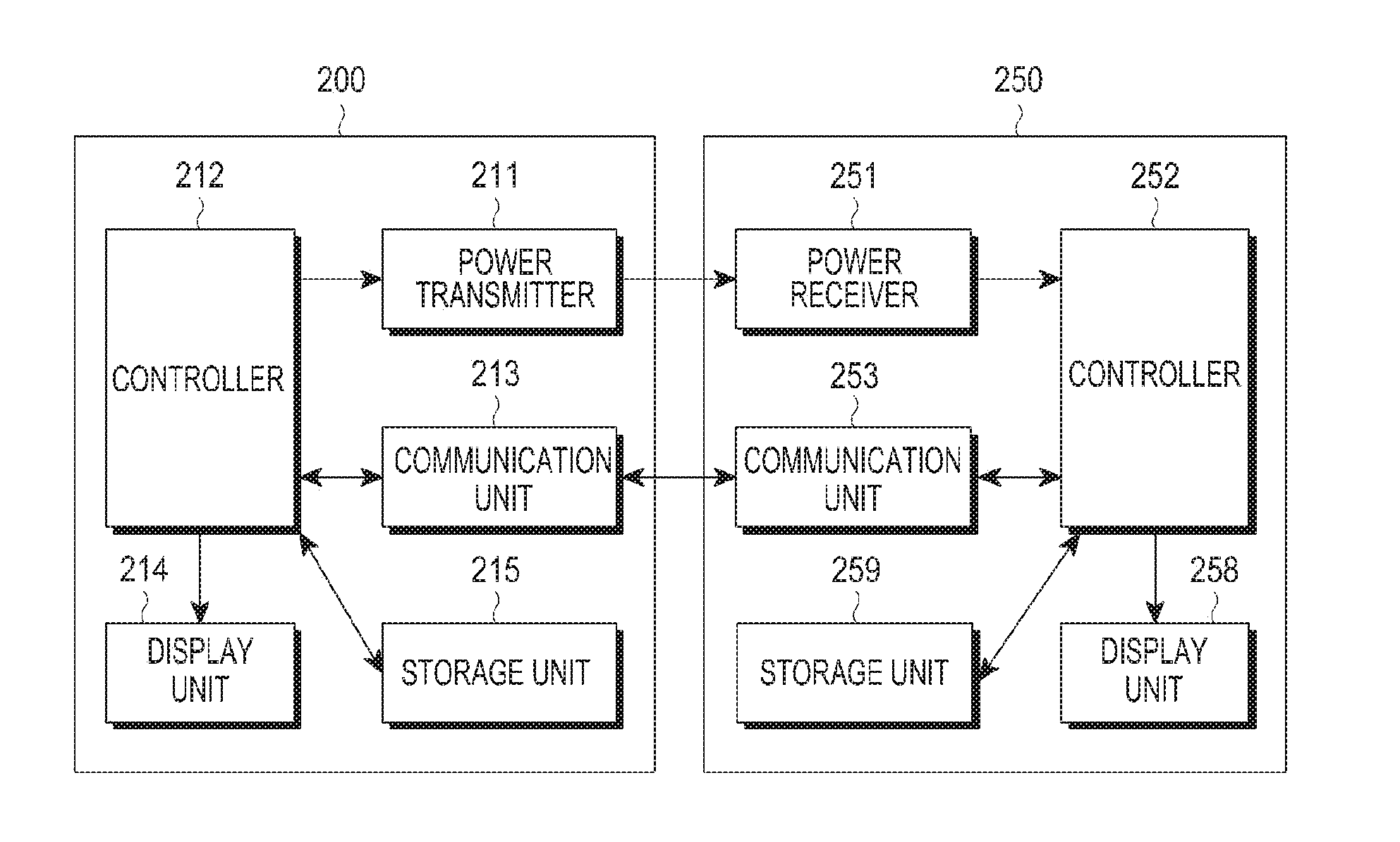
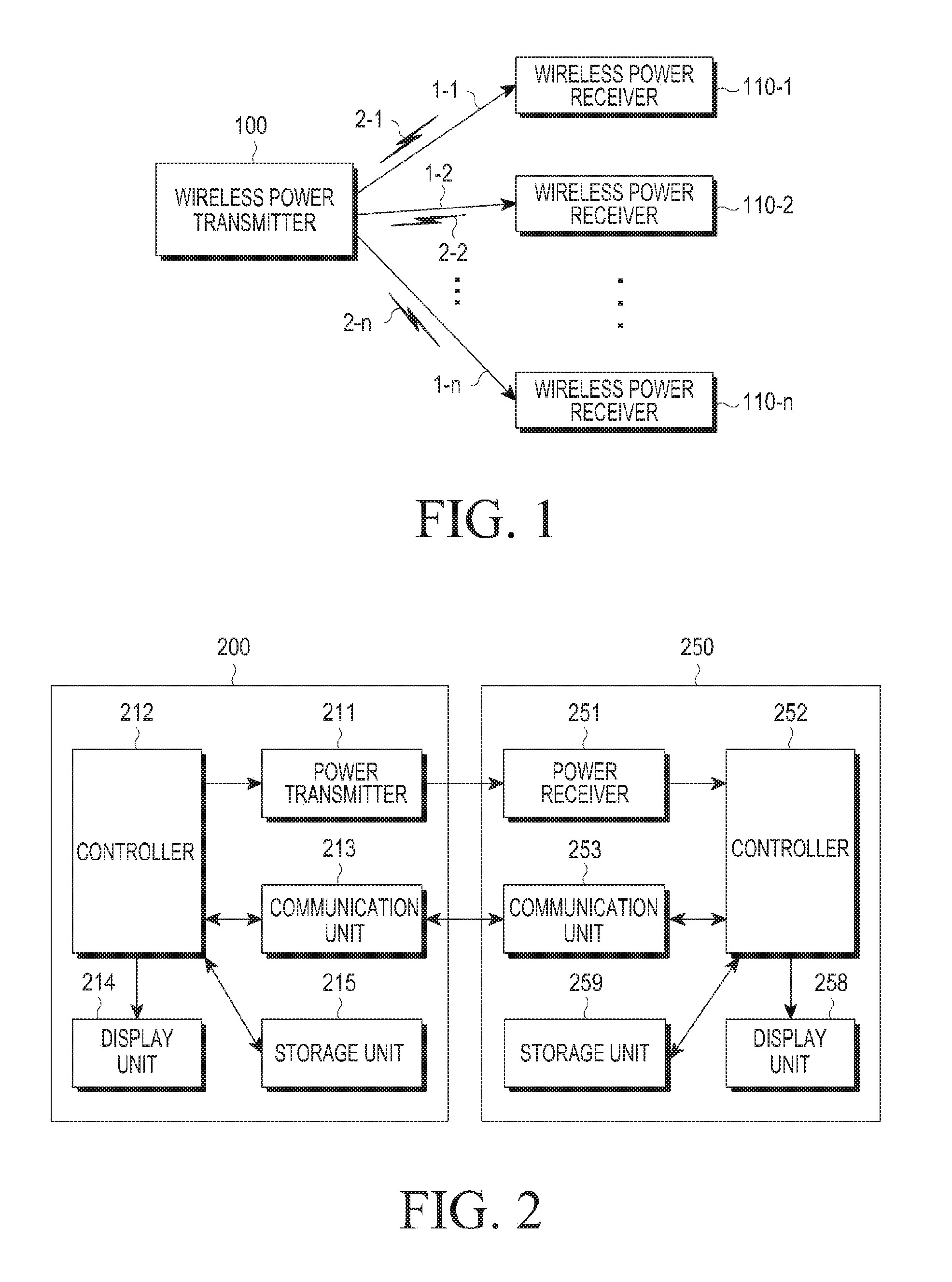
[0052]FIG. 1 illustrates an overall operation of a wireless charging system. Referring to FIG. 1, the wireless charging system includes a PTU 100 and PRUs 110-1, 110-2, and 110-n.

[0053]The PTU 100 may wirelessly send power 1-1, 1-2, and 1-n to the PRUs 110-1, 110-2, and 110-n, respectively, when authenticated by a predetermined authentication process.

[0054]The PTU 100 may form electrical connections with the PRUs 110-1, 110-2, and 110-n. For example, the PTU 100 may transmit electromagnetic waves of wireless power to the PRUs 110-1, 110-2, and 110-n.

[0055]The PTU 100 may perf...


PUM


Abstract

A wireless power receiver (PRU) and a method for generating a load of the PRU for detecting the PRU in a wireless charging system are provided. The method includes receiving a wireless power signal from a wireless power transmitter (PTU), rectifying the received wireless power signal into a direct current (DC) signal, and generating a load for detecting the PRU by controlling a current flowing across a resistor connected in parallel with a load charged with power of the DC signal.

Description

PRIORITY[0001]This application claims priority under 35 U.S.C. §119(a) to Korean Patent Application Serial No. 10-2015-0035282, which was filed in the Korean Intellectual Property Office on Mar. 13, 2015, the entire disclosure of which is incorporated herein by reference.BACKGROUND[0002]1. Field of the Disclosure[0003]The present disclosure relates generally to wireless charging, and more specifically, to a wireless power receiver and methods for generating a load of the wireless power receiver in a wireless charging system.[0004]2. Description of the Related Art[0005]A mobile terminal, such as a mobile phone or a personal digital assistant (PDA), is generally powered by a rechargeable battery. To recharge the battery, a separate charger is used. Typically, the charger and the battery have separate contacts for electrical connection therebetween.[0006]However, these type of contacts, which normally project outward, may be easily contaminated by foreign bodies, which may inhibit the ...

Claims


Application Information

Patent Timeline
Patent Type & Authority Applications(United States)
IPC IPC(8): H02J5/00H02J7/02H02J50/60
CPCH02J5/005H02J7/025H02J50/60H02J50/12H02J50/40H02J50/80H02J50/10H02J50/90H02J7/00034H04B5/0037
Inventor LEE, KYUNG-WOOJUNG, HEE-WON
Owner SAMSUNG ELECTRONICS CO LTD
Why Eureka
Try Eureka