Vacuum Condenser

a vacuum pump and condenser technology, applied in the field of vacuum pumps, can solve the problems of limited commercial use of venturi vacuum pumps, device not fully addressing the requirements, and specialized devices, and achieve the effect of reducing pressur

Inactive Publication Date: 2016-09-22
HARMAN JAYDEN DAVID +4
View PDF15 Cites 9 Cited by
  • Summary
  • Abstract
  • Description
  • Claims
  • Application Information

AI Technical Summary

Benefits of technology

[0007]Accordingly the invention resides in a vacuum condenser adapted to reduce pressure in an enclosure containing a secondary liquid and thereby cause the accelerated production of vapor from the secondary liquid by the passage of a primary liquid through the vacuum condenser and whereby the vapor produced is absorbed by th

Problems solved by technology

However, to date the commercial use of venturi vacuum pumps has been limited and somewhat specialized.
However, testing has revealed that while this is so at a general sense, when the aim is to produce substantial rate of production of vapor an

Method used


Image

  • Vacuum Condenser
  • Vacuum Condenser
  • Vacuum Condenser

Examples


first embodiment

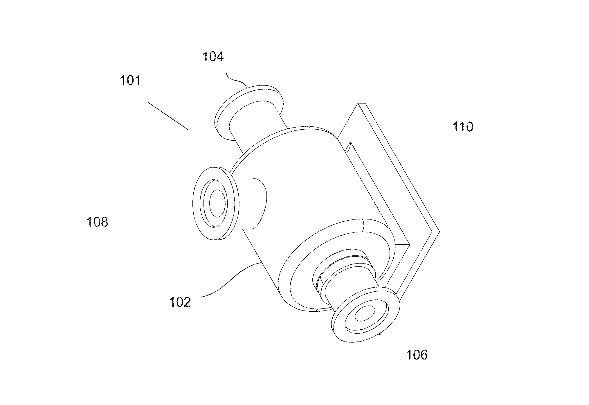
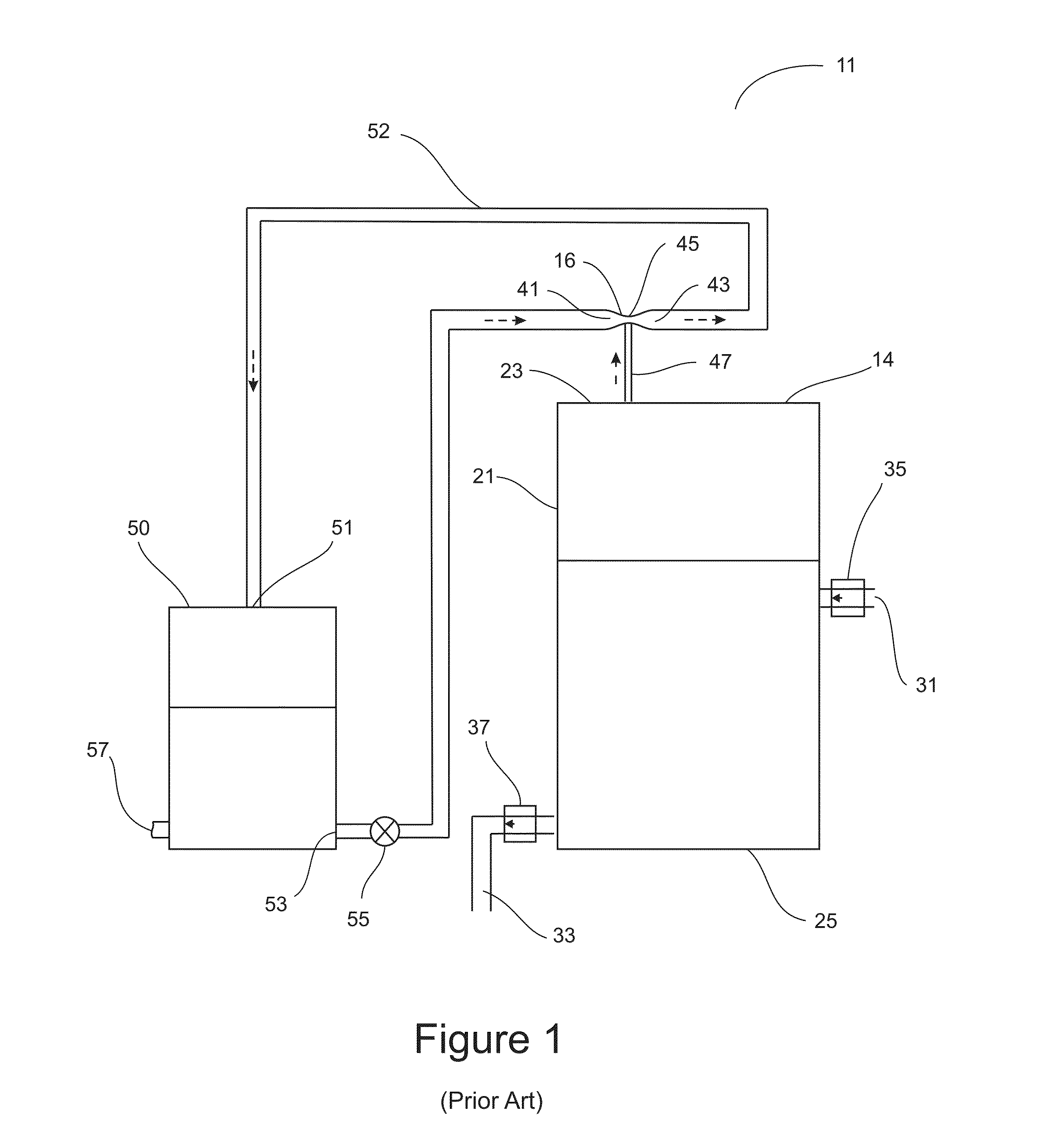
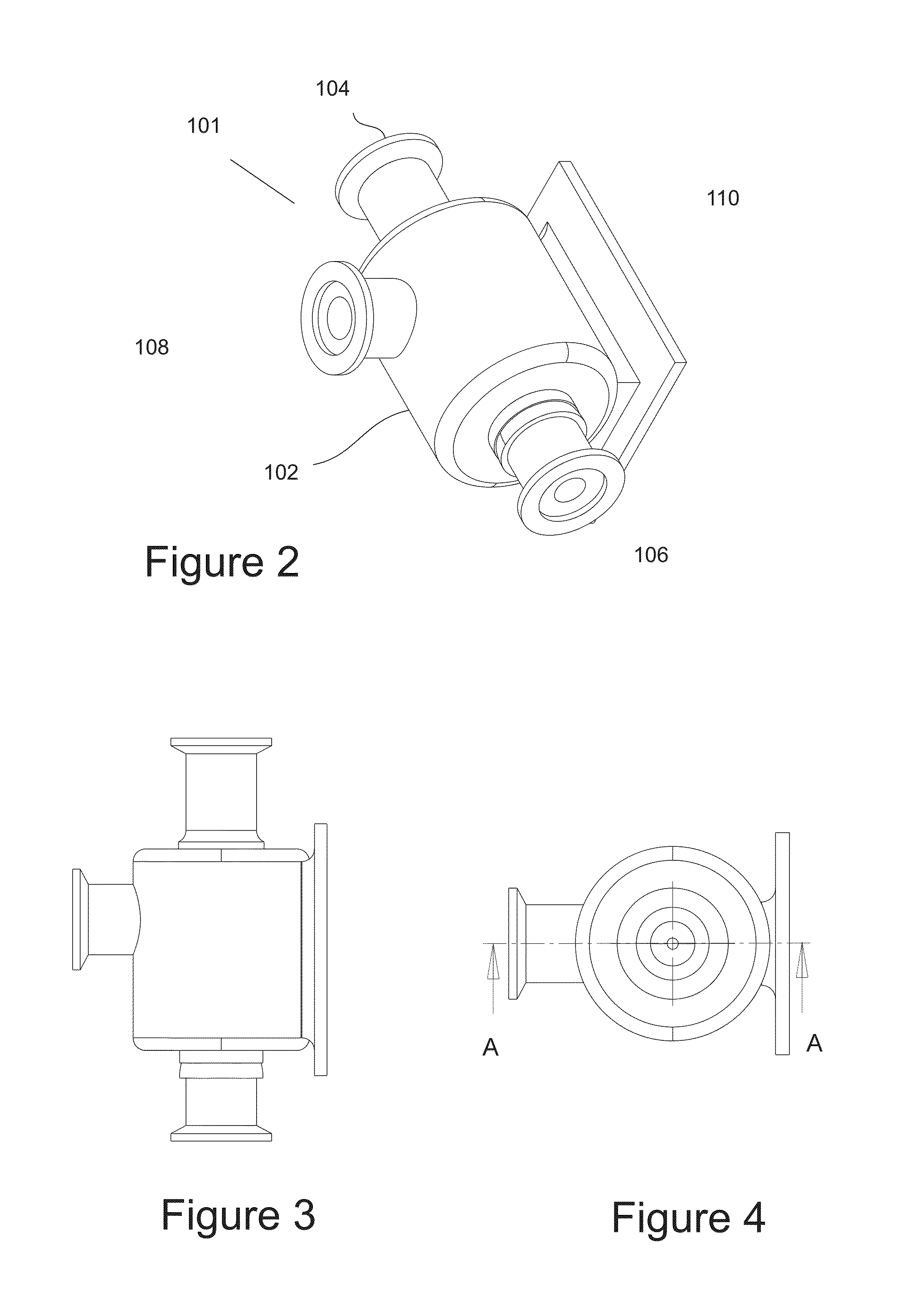
[0041]The distillation system 11 according to the disclosure comprises an evacuation chamber 14 adapted to receive a quantity of liquid (secondary liquid) to be distilled, for example a water mixture. The evacuation chamber 14 is provided with an inlet 31 and a drain or outlet 33. A vacuum condenser 16 is arranged to extract vapor from the upper portion of the chamber 14. The vacuum condenser 16 comprises a venturi inlet 41, a venturi outlet 43 and a narrowed venturi throat section 45 intermediate the venturi inlet 41 and the venturi outlet 43. A port 47 connects the low pressure venturi throat section 45 of the vacuum condenser 16 with the evacuation chamber 14.

[0042]In operation, the vacuum condenser 16 evacuates the evacuation chamber to a pressure below that of the vapor pressure of the secondary water in the evacuation chamber 14. Such vapor condenses almost immediately upon entering the water stream, the primary liquid in this case, flowing through the venturi throat section 4...

second embodiment

[0044]the vapor absorption system of WO2011 / 123904 as shown in FIG. 2 of that specification added a heat exchanger 60 into the secondary water to enable heat to be transferred to the secondary water from in a more flexible mariner than in the case of the heat exchanger.

fifth embodiment

[0045]the vapor absorption system of WO2011 / 123904 as shown in FIG. 5 of that specification provided means for extracting heat from the primary flow for re-use and lowering the primary flow back to its desired input temperature.

[0046]The disclosure WO2011 / 123904 made it clear that it was desirable to use a vacuum condenser of optimum efficiency but until now it has not been appreciated what was necessary to provide such a device. This is because those skilled in the art are not familiar with this application of a venturi vacuum for the purpose of absorbing substantial quantities of vapor. The object of the vapor absorption system is to cause as much as possible of the secondary liquid to be vaporized and then condensed with maximum efficiency. It is noted within the disclosure WO2011 / 123904 that to cause the secondary liquid to change phase to vapor, energy must be input into the secondary liquid to provide the latent heat of vaporization. Various proposals are given for the ways to...


PUM

PropertyMeasurementUnit
Temperatureaaaaaaaaaa
Lengthaaaaaaaaaa
Pressureaaaaaaaaaa

Abstract

A vacuum condenser adapted to reduce pressure in an enclosure containing a secondary liquid and thereby cause the accelerated production of vapor from the secondary liquid by the passage of a primary liquid through the vacuum condenser and whereby the vapor produced is absorbed by the primary liquid within the vacuum condenser by being entrained and condensed within the primary liquid wherein the vacuum condenser is configured to cause the operating temperature of the secondary liquid within the enclosure to maintain a stable minimum temperature for a predetermined substantial rate of production of vapor.

Description

CROSS-REFERENCE TO RELATED APPLICATIONS[0001]The present application is a national phase application of PCT application PCT / US2014 / 000082 filed May 5, 2014, which claims the priority benefit of U.S. provisional application No. 61 / 854,895 filed May 3, 2013, the disclosures of which are incorporated herein by reference.FIELD OF THE INVENTION[0002]The present invention relates to a venturi vacuum pump which acts as a vacuum condenser.BACKGROUND[0003]Venturi vacuum pumps are well known and commonly used in applications where a gas such as air or a liquid such as water is forced under pressure through a venturi formation thereby providing a reduced pressure in the vicinity of the constricted or throat region of the venturi. The reduced pressure can be communicated by suitable porting for use in various applications. However, to date the commercial use of venturi vacuum pumps has been limited and somewhat specialized.[0004]The publication WO2011 / 123904 by Harman et. al. discloses a new ap...

Claims


Application Information

Patent Timeline
IPC IPC(8): B01D5/00C02F1/10B01D1/14
CPCB01D5/0045B01D5/0036B01D5/006C02F2301/063B01D1/14C02F1/10B01D5/0003
Inventor HARMAN, JAYDEN DAVIDWOODGATE, PETERPENNEY, KIMBERLYWEBSTER, BRUCEFARSAD, KASRA
Owner HARMAN JAYDEN DAVID
Why Eureka
Try Eureka