
Exhaust gas sampling apparatus and exhaust gas analysis system

a technology of exhaust gas sampling and exhaust gas, which is applied in mechanical equipment, machines/engines, instruments, etc., can solve the problems of increasing the size and complexity of the system, affecting the accuracy of dilution ratio, and becoming more difficult for exhaust gas sampling apparatus, so as to simplify the configuration of the whole exhaust gas sampling apparatus.

Inactive Publication Date: 2016-09-22
HORIBA LTD
View PDF4 Cites 5 Cited by
  • Summary
  • Abstract
  • Description
  • Claims
  • Application Information

AI Technical Summary

Benefits of technology

The exhaust gas sampling apparatus described in this patent can achieve consistent dilution ratios at different stages, making it difficult for flow rate errors to affect the dilution ratios. This simplifies the process of obtaining accurately diluted exhaust gas at the final stage. By ensuring uniform dilution ratios at all stages, this design also reduces the complexity of the flow rate control mechanisms needed and allows for a simpler standardized flow rate control mechanism to be used.

Problems solved by technology

As a dilution ratio is increased, an error in flow rate of dilution air flowing into a diluter, and / or an error in flow rate of exhaust gas got by the diluter become more likely to affect the accuracy of the dilution ratio.
For this reason, as a dilution ratio is increased, it becomes more difficult for an exhaust gas sampling apparatus including only a single-stage dilution flow path to dilute exhaust gas with a predetermined accuracy.
In addition, in order to respond to various dilution ratios, it has been considered that variable flow rate ranges of the respective flow rate controllers must be set to be large, thus causing increases in size and complexity of a system.

Method used


Image

  • Exhaust gas sampling apparatus and exhaust gas analysis system
  • Exhaust gas sampling apparatus and exhaust gas analysis system
  • Exhaust gas sampling apparatus and exhaust gas analysis system

Examples


Embodiment Construction

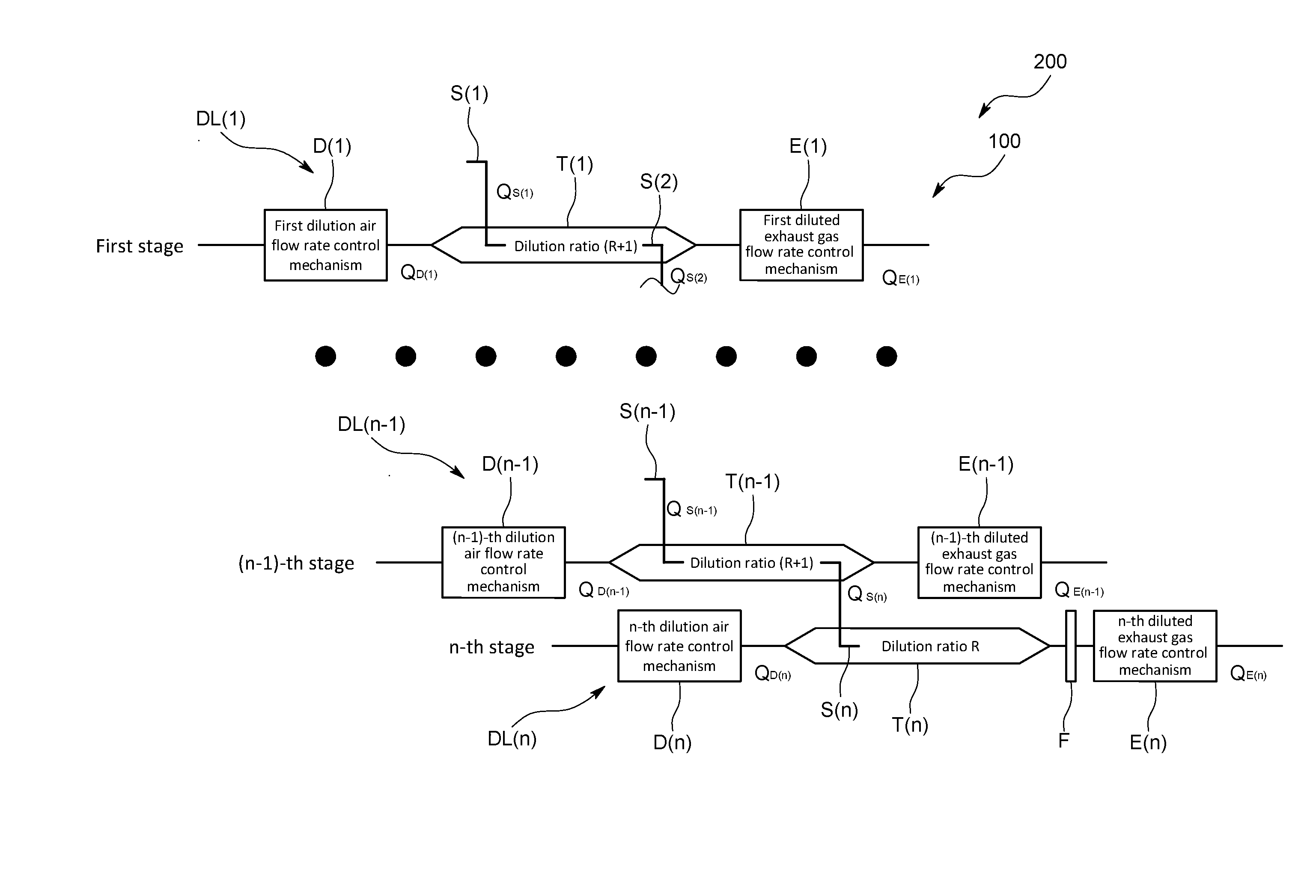
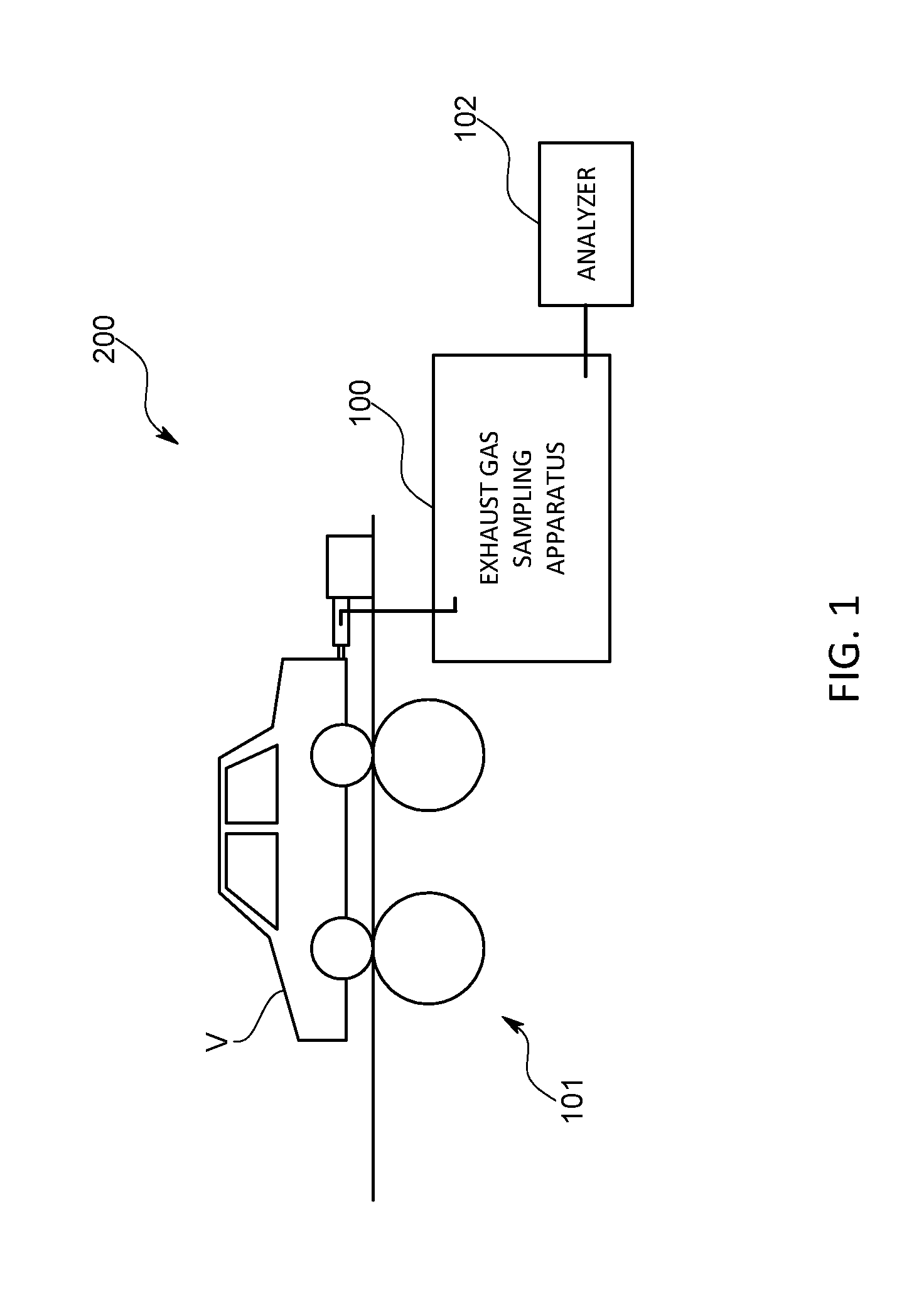
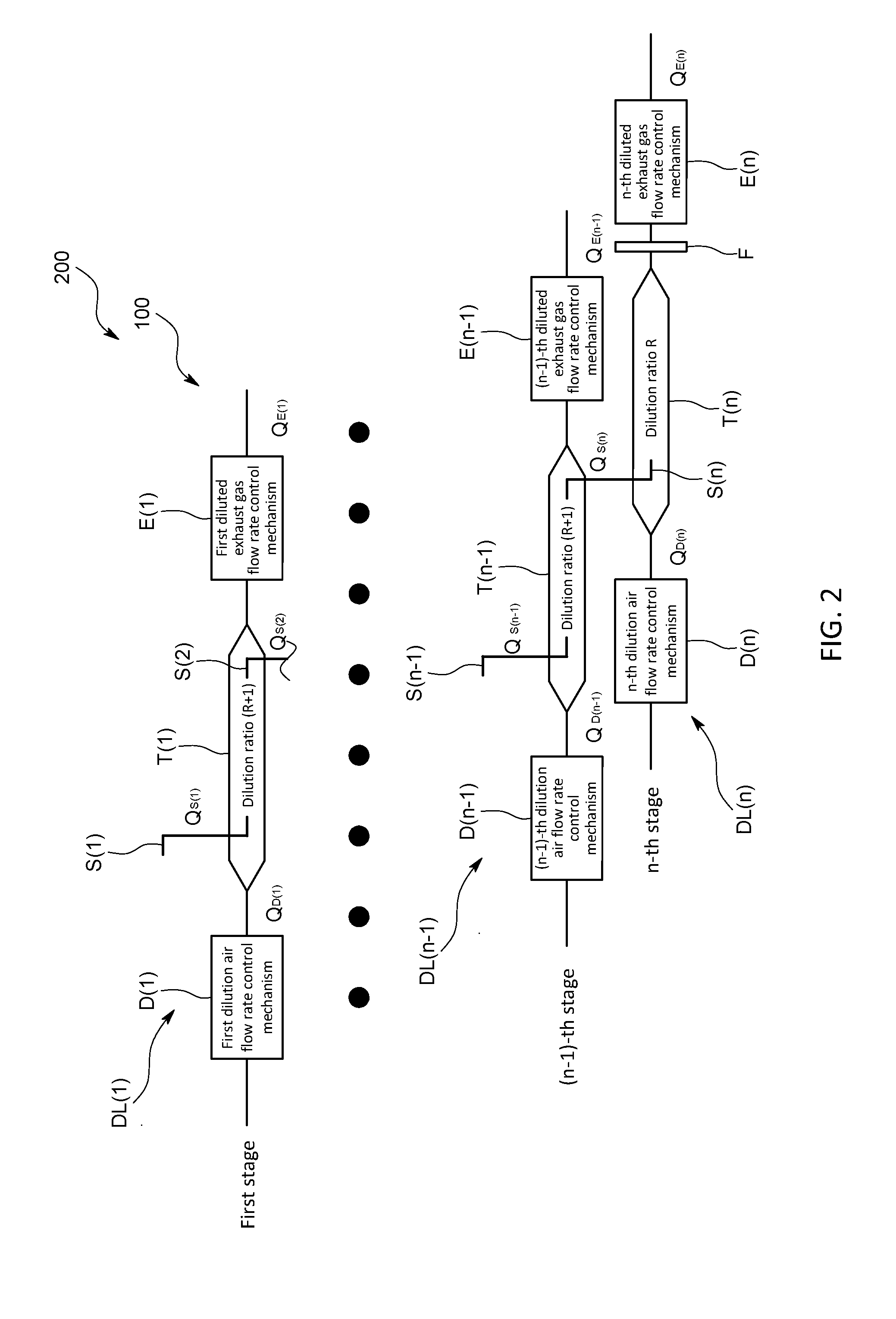
[0035]An exhaust gas analysis system 200 and an exhaust gas sampling apparatus 100 according to one embodiment of the present invention will be described with reference to FIGS. 1 and 2.

[0036]The exhaust gas sampling apparatus 100 according to the present embodiment is one that as illustrated in FIG. 1, constitutes part of the exhaust gas analysis system 200 adapted to measure the amount of particulate matter (hereinafter also referred to as PM) having a predetermined particle size contained in exhaust gas. More specifically, from the side surface of an attachment pipe attached to a tail pipe of a vehicle V making a test run on a chassis dynamometer 101, a sampling pipe S of the exhaust gas sampling apparatus 100 is inserted into the attachment pipe. In addition, part of the raw exhaust gas discharged from the vehicle V is collected through the sampling pipe S, and diluted to a predetermined concentration by the exhaust gas sampling apparatus 100. The diluted exhaust gas resulting f...


PUM

PropertyMeasurementUnit
flow rateaaaaaaaaaa
flow ratesaaaaaaaaaa
particle sizeaaaaaaaaaa

Abstract

In order to provide an exhaust gas sampling apparatus that makes it possible to simplify the entire system using a simple structure flow rate control mechanism having a small variable flow rate range as well as making the accuracy of an exhaust gas dilution ratio higher than before, the exhaust gas sampling apparatus is configured as an exhaust gas sampling apparatus that makes a multistage dilution. In addition, the exhaust gas sampling apparatus is configured to, given that a dilution ratio determined by an n-th diluter in a dilution flow path at an n-th stage as a final stage is R, make dilution ratios determined by diluters in dilution flow paths at the respective stages other than the n-th stage as the final stage substantially equal to (R+1).

Description

CROSS-REFERENCE TO RELATED APPLICATION[0001]This application claims priority to JP Application No. 2015-058695, filed Mar. 20, 2015, the disclosure of which is incorporated in its entirety by reference herein.TECHNICAL FIELD[0002]The present invention relates to an exhaust gas sampling apparatus that includes a multistage dilution flow path to dilute exhaust gas through multistage dilution.BACKGROUND ART[0003]For example, when measuring the amount of particulate matter (hereinafter also referred to as PM) having a predetermined particle size contained in exhaust gas, the exhaust gas is diluted at a large dilution ratio, and the diluted exhaust gas is passed through a filter at a predetermined flow rate.[0004]As a dilution ratio is increased, an error in flow rate of dilution air flowing into a diluter, and / or an error in flow rate of exhaust gas got by the diluter become more likely to affect the accuracy of the dilution ratio. For this reason, as a dilution ratio is increased, it b...

Claims


Application Information

Patent Timeline
Patent Type & Authority Applications(United States)
IPC IPC(8): F01N11/00G01N15/06F01N3/021G01M15/10F01N9/00F01N3/05
CPCF01N11/007F01N9/00F01N3/05G01N2015/0046G01M15/102G01N15/06F01N2550/14F01N3/021G01N1/2252G01N2001/2255G01N1/2205G01N2001/2264
Inventor OTSUKI, YOSHINORI
Owner HORIBA LTD
Learn More