EPR Microwave Cavity for Small Magnet Airgaps

a micro-epr and air gap technology, applied in the field of micro-wave resonators, can solve the problems of direct affecting the design and performance of epr probe heads, the standard air-filled epr probe heads do not fit inside the usual cryostat, and are highly difficult to achieve, so as to minimize the influence of the microwave mode in the resonator is eliminated, and the influence of the microwave mode is minimized.

Active Publication Date: 2016-09-22
BRUKER BIOSPIN
View PDF7 Cites 6 Cited by
  • Summary
  • Abstract
  • Description
  • Claims
  • Application Information

AI Technical Summary

Benefits of technology

[0032]A further class of embodiments of the invention is characterized by at least one set of coils for creating a low frequency magnetic field traversing the cavity body and a sample tube, the coils being located at least partly inside the resonator and the connection to the outside of the cavity body being realized by openings in the side walls of the cavity body which are perpendicular to the z-axis. By this means the applied low frequency magnetic field is coupled very efficiently to the EPR sample as it is very close to the sample. In this aspect the turns of the coil are not fully contained in the resonator thereby minimizing their influence on the microwave mode in the r...

Problems solved by technology

For EPR experiments at X-band (8-12 GHz) or higher frequencies the size of magnet gap or solenoid bore becomes an important factor in the ownership cost of the EPR system.
Such a size constraint also directly affects the design and performance of EPR probe heads.
For example, at X-band or lower frequencies the standard air-filled EPR probe heads do not fit inside usual cryostats.
This is highly difficult to accomplish due to space constraints if the cavity has circular symmetry.
Attempts to use a coaxial stack of two or more dielectric elements for cavity loading have also been considered but proved to be more difficult than helpful.
Even more, for an increasingly larger number of modern EPR applications, the microwave cavity geometries using a single element for dielectri...

Method used


Image

  • EPR Microwave Cavity for Small Magnet Airgaps
  • EPR Microwave Cavity for Small Magnet Airgaps
  • EPR Microwave Cavity for Small Magnet Airgaps

Examples


Embodiment Construction

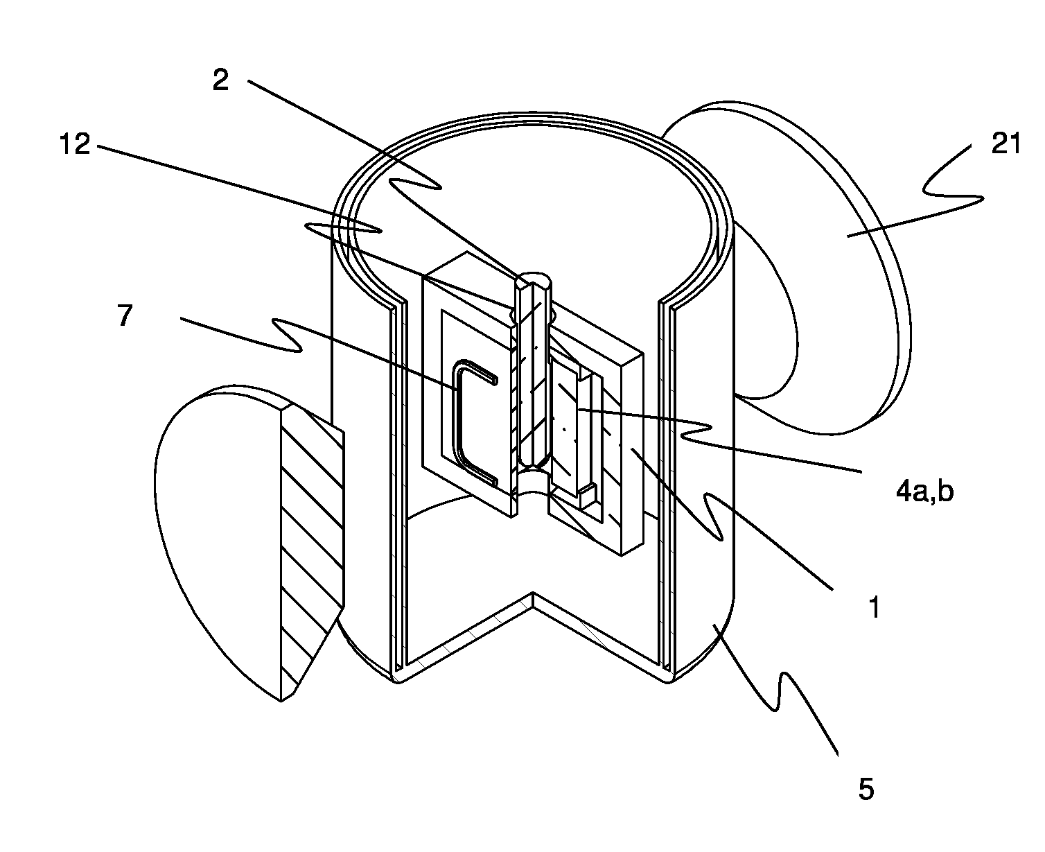
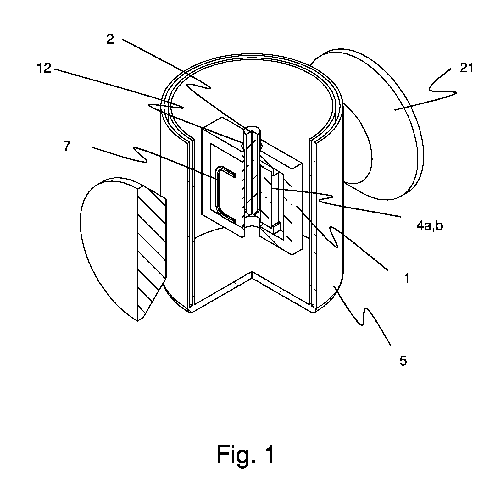
[0051]A simplified example of the novel EPR experimental setup according to the present invention is shown in FIG. 1. The dielectric 4a,b loaded flat microwave cavity 1, is shown accompanied by a variable temperature cryostat 5, magnet poles 21 of an external magnet creating a main static magnetic field and a modulation coil 7 responsible for creating the modulation magnetic field traversing the EPR cavity and the paramagnetic sample 2 in an EPR experiment. The sample mostly consists of a tube holding a substance to be measured. When describing features of the resonator related to the position of the sample it is understood this equivalent to the space provided for accommodation of the sample. For clarity all other details concerning mechanical or microwave standard implementations were suppressed (various supports, coaxial microwave transmission line and microwave coupling structure necessary to excite the microwave resonance which is relevant for EPR use).

[0052]It is an object of ...


PUM


Abstract

A microwave resonator for an EPR probe head has a metal cavity body (1) supporting an electromagnetic microwave resonance mode. The metal cavity body (1) has an opening for inserting a sample tube (2) to a center position of the resonator. The center of the opening and the center position of the resonator define an x-axis. The cavity body also has an opening for transmitting microwave radiation into the resonator. Two dielectric elements (4a, 4b) are located symmetrically to the E-field nodal plane containing the x-axis and a z-axis perpendicular to the x-axis. Each dielectric element is geometrically formed and positioned such that it provides an equal overlap with a local maximum of the microwave electric field energy. The microwave resonant cavity has a thin planar shape and the resonator is loaded with two dielectric elements, placed symmetrically relative to the central EPR sample.

Description

[0001]This application claims Paris convention priority from EP 15 159 643.4, filed Mar. 18, 2015, the entire disclosure of which is hereby incorporated by reference.BACKGROUND OF THE INVENTION[0002]The present invention relates to a microwave resonator for an EPR (=“electron paramagnetic resonance”) probe head comprising: a metal cavity body supporting an electromagnetic microwave resonance mode, the microwave mode having an even number of local maxima of microwave electric field energy, at least one opening for inserting a sample tube to a center position of the resonator, the center of the opening and the center position of the resonator defining an x-axis, at least one opening for transmitting microwave radiation into the resonator, at least two identical dielectric elements located symmetrically to the plane known as “E-field nodal plane” which contains the x-axis and a z-axis perpendicular to the x-axis.[0003]A device of this type is known from U.S. Pat. No. 3,757,204.[0004]In...

Claims


Application Information

Patent Timeline
IPC IPC(8): G01R33/343H01P7/10G01R33/60
CPCG01R33/343H01P7/10G01R33/60H01P1/207G01R33/345
Inventor PRISECARU, IONHOEFER, PETER
Owner BRUKER BIOSPIN
Why Eureka
Try Eureka