Electric power supply system

a technology of electric power supply and power supply system, which is applied in the direction of process and machine control, battery/fuel cell control arrangement, instruments, etc., can solve problems such as limited current, achieve uniform temperature increase, reduce temperature variation, and efficiently and quickly increase the temperature of the electric power storage apparatus

Active Publication Date: 2016-09-22
TOYOTA JIDOSHA KK
View PDF11 Cites 7 Cited by
  • Summary
  • Abstract
  • Description
  • Claims
  • Application Information

AI Technical Summary

Benefits of technology

[0027]Through this configuration, during increasing the temperature of the electric power storage apparatus with the operation of the converter using the second reactor, it is possible to suppress variation in temperature among the battery cells separately arranged in the units, thereby attaining uniform temperature increasing of the electric power storage apparatus.
[0028]Preferably, the first reactor and the second reactor have an equal inductance. Through this configuration, at the time of performing switching between the first reactor and the second reactor by controlling the first switch and the second switch, it is possible to stabilize the operation of the converter before and after the switching.
[0029]According to the above aspect of the present invention, in an electric power supply system equipped with an electric power storage apparatus and a converter including a reactor, it is possible to efficiently and rapidly increase a temperature of the electric power storage apparatus in a low temperature state.

Problems solved by technology

Unfortunately, there is room for improvement of energy efficiency in the configuration of JP 2014-87081 A because, from energy of passing current of the electric power storage apparatus, only heat generated due to the Joule heat from an inside of the electric power storage apparatus can be used for increasing the temperature of the electric power storage apparatus.
In light of this point, there is a concern that during increasing the temperature of the electric power storage apparatus, the current is restricted.

Method used


Image

  • Electric power supply system
  • Electric power supply system
  • Electric power supply system

Examples


first embodiment

Variation of First Embodiment

[0119]In the variation of the first embodiment, a preferable arrangement structure of the reactor for temperature increasing L1b in the battery pack 80 will be described.

[0120]FIG. 6 is a circuit diagram of the reactor for temperature increasing, and FIG. 7 is a block diagram conceptually explaining the arrangement manner of the reactor for temperature increasing in the battery pack.

[0121]With reference to FIG. 6 and FIG. 7, the reactor for temperature increasing L1b is configured by a plurality of reactor elements 12a to 12d connected in series. The main battery 10 is divided into a plurality of battery units 11a to 11d. Each of the battery units 11a to 11d is configured to include a plurality of battery cells (not shown) that are electrically connected. The battery units 11a to 11d are electrically connected to one another. For example, the main battery 10 is configured by the battery units 11a to 11d connected in series.

[0122]As shown in FIG. 7, the r...

second embodiment

[0136]In the following second and third embodiments, in addition to the reactor switching control in the first embodiment, a reactor switching control additionally carried out will be described. In the following embodiments, overlapping description regarding parts to which the same configurations and the same controls as those in the first embodiment are applied will be omitted.

[0137]FIG. 10 is a flowchart showing control processing for reactor switching of the converter in the electric power supply system according to the second embodiment. The control processing in accordance with the flowchart as shown in FIG. 10 is repetitively carried out with predetermined time intervals if the main battery 10 is in a non-low temperature state (if NO is determined in S120 of FIG. 3).

[0138]With reference to FIG. 10, the control unit 50 determines whether or not the hybrid vehicle 100 is in a silent drive mode in step S150. In the present embodiment, the “silent drive mode” denotes a drive state...

third embodiment

[0156]FIG. 13 is a flowchart explaining the witching processing of the reactor of the converter 15 according to the third embodiment. The control processing according to the flowchart as shown in FIG. 13 is repetitively executed with predetermined time intervals in the non-low temperature state of the main battery 10 (if NO is determined in S120 of FIG. 3).

[0157]With reference to FIG. 13, in step S170, the control unit 50 determines whether or not any abnormality occurs in the normal reactor L1a. The determination in step S170 may be carried out based on a diagnostic code for the hybrid vehicle 100.

[0158]At the time of abnormality in the normal reactor L1a, the control unit 50 advances the processing to step S180 to determine whether or not the main battery 10 is in a high temperature state. The determination in step S180 can be executed in the same manner as that in step S160 of FIG. 10.

[0159]If abnormality occurs in the normal reactor L1a, and the main battery 10 is not in the hig...


PUM


Abstract

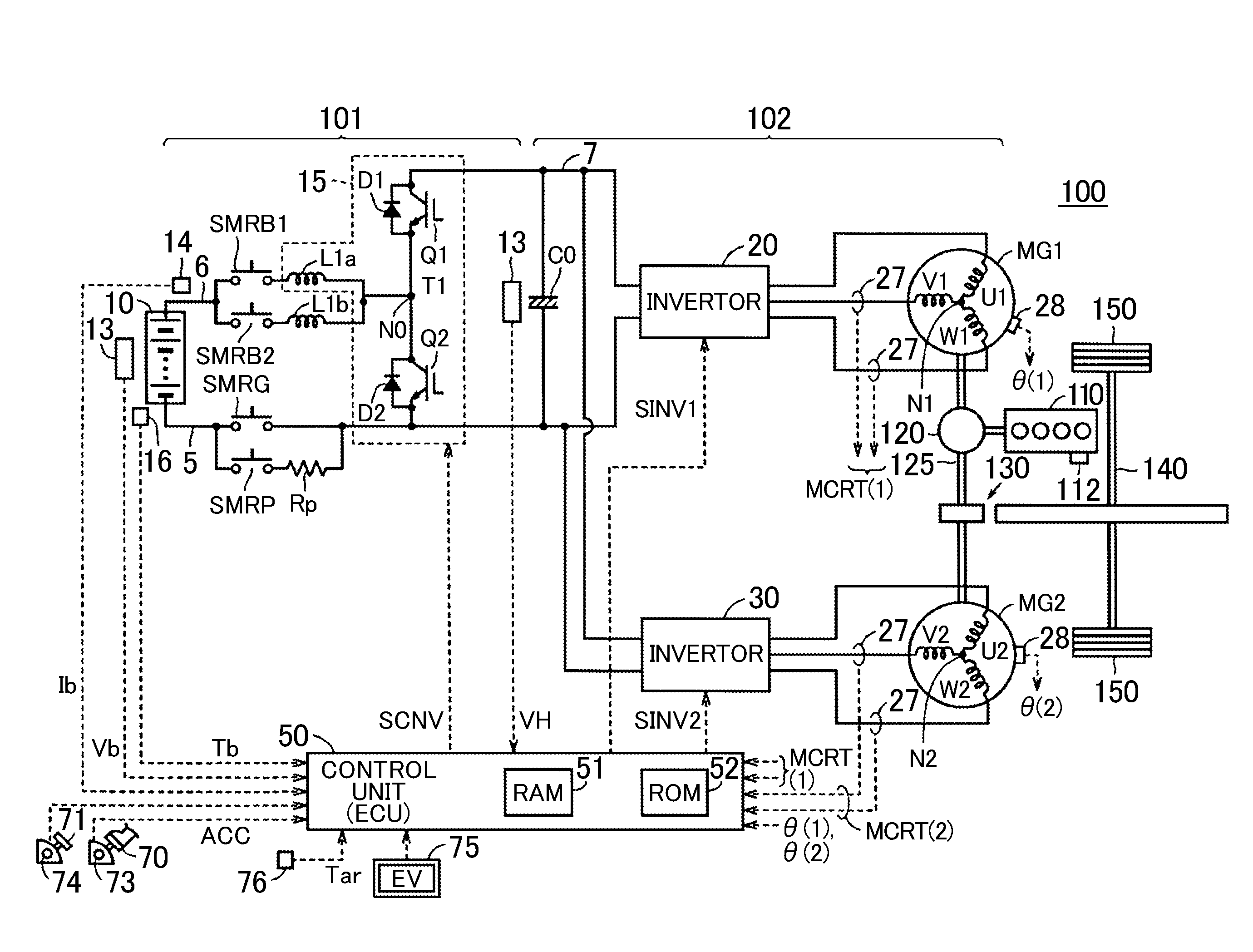
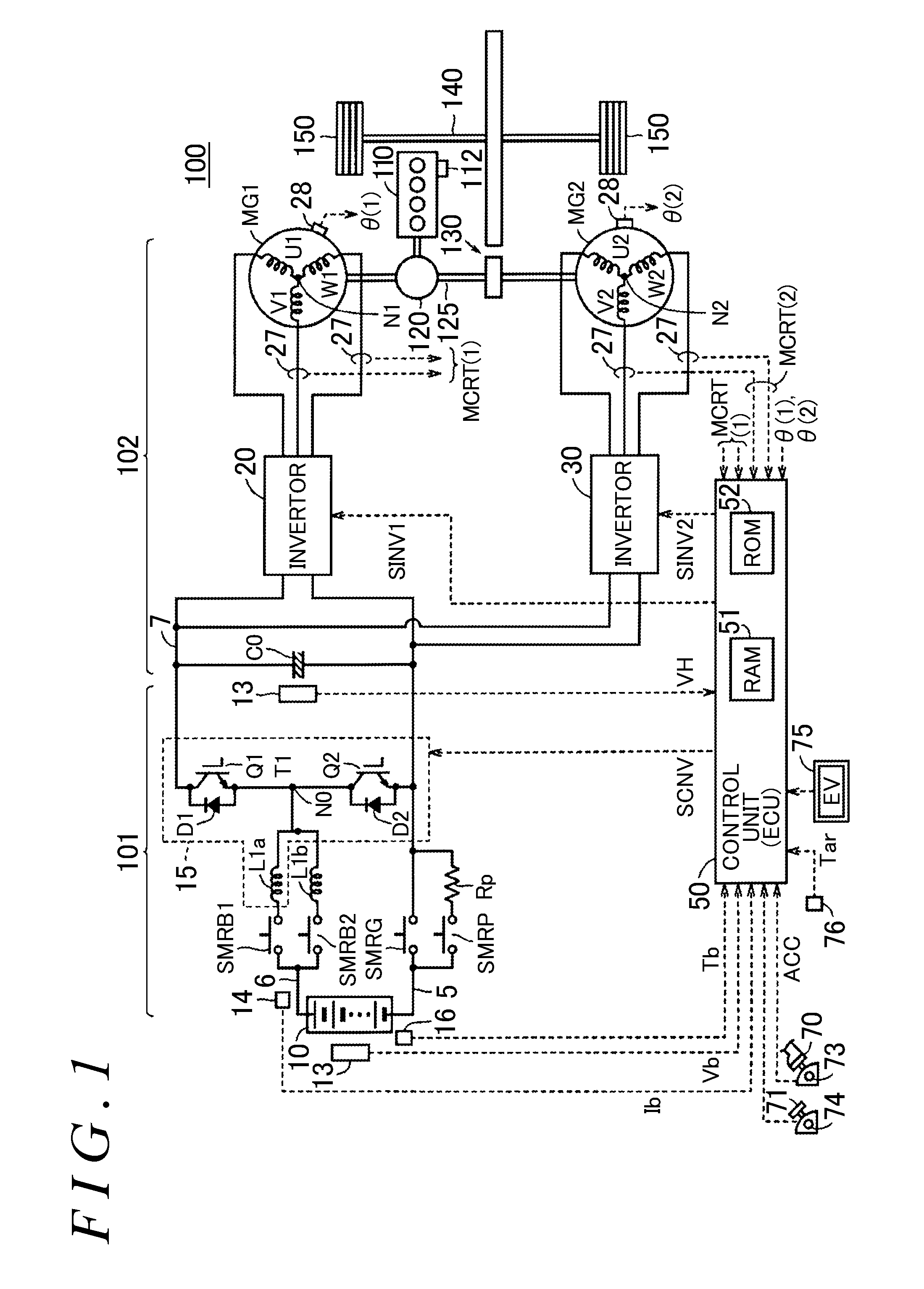
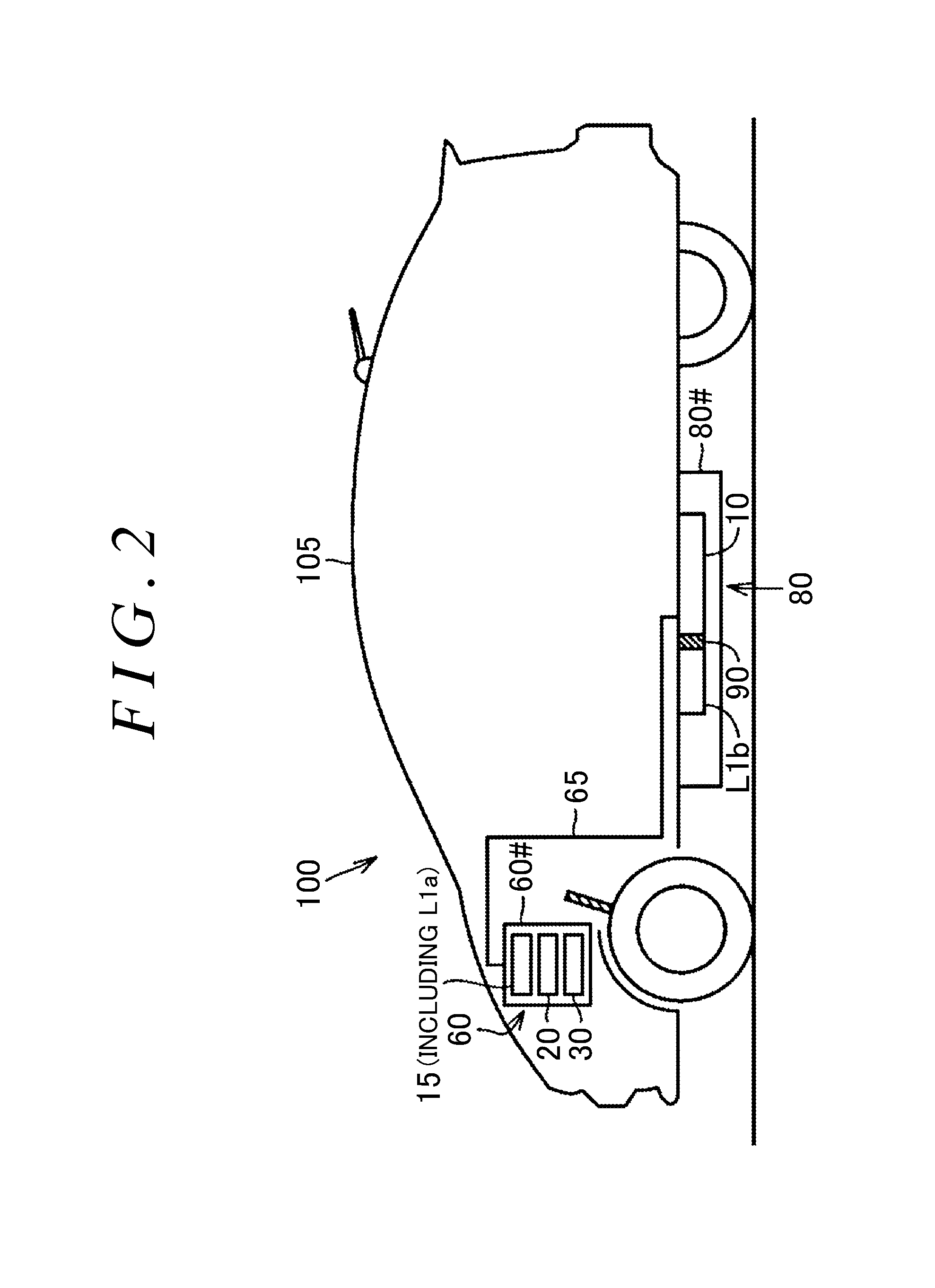
A converter can selectively use reactors through an ON-OFF control on relays by an electronic control unit. The first reactor is disposed as a component of the converter separately from a main battery. On the other hand, the second reactor is so disposed as to have a heat transfer path between the second reactor and the main battery. At least based on the output from the temperature sensor, in a low temperature state of the main battery, the electronic control unit turns off the first relay, and turns on the second relay, thereby configuring a reactor of the converter by using the second reactor.

Description

INCORPORATION BY REFERENCE[0001]The disclosure of Japanese Patent Application No. 2015-055901 filed on Mar. 19, 2015 including the specification, drawings and abstract is incorporated herein by reference in its entirety.BACKGROUND OF THE INVENTION[0002]1. Field of the Invention[0003]The present invention relates to an electric power supply system, and more particularly to an electric power supply system equipped with an electric power storage apparatus and a converter that including a reactor.[0004]2. Description of Related Art[0005]An electric power supply system equipped with an electric power storage apparatus and a converter including a reactor and switching elements is described in Japanese Patent Application Publication No. 2014-87081.[0006]In JP 2014-87081 A, the converter is configured such that a first reactor and a second reactor that have different inductances are switched via a relay. In addition, it is described that during increasing the temperature of the electric pow...

Claims


Application Information

Patent Timeline
Patent Type & Authority Applications(United States)
IPC IPC(8): H02M3/158B60L3/00B60L11/18
CPCH02M3/158B60L11/1803Y10S903/904B60L3/0023B60L11/1872H01M10/615H01M10/625H01M10/635H01M10/667Y02T90/16B60L3/0092B60L2240/545B60L2240/662B60L2270/145B60L58/24B60L50/64Y02T10/70Y02T10/72Y02E60/10B60L3/0046
Inventor ARAI, KUNIHIKO
Owner TOYOTA JIDOSHA KK
Why Eureka
Try Eureka