LED support with reception surface and electrical connection by wire-bonding

a technology of wire bonding and support, applied in the direction of fixed installation, transportation and packaging, light and heating apparatus, etc., can solve the problems of limited cooling capacity, limited positioning accuracy, and limited cooling capacity in this construction, and achieve optimized cooling of light sources, less accuracy, and great accuracy

Active Publication Date: 2016-09-29
VALEO VISION SA
View PDF0 Cites 8 Cited by
  • Summary
  • Abstract
  • Description
  • Claims
  • Application Information

AI Technical Summary

Benefits of technology

[0061]The measures of the invention are advantageous in that they make it possible to carry out the positioning of the light sources with great accuracy directly on the substrate that acts as frame and reference part. The cooling of the light sources is also optimized. The electrical power supply circuit or circuits can be positioned and fixed with less accuracy than the light sources, notably in proportion to the size of their zones of contact with the metal wires.
[0062]The structures protruding from the support and defining reception planes or surfaces for the light sources make it possible to give the latter a specific orientation without requiring other components. Notably, the sources can be raised relative to the power supply circuit in order to avoid any risk of shadow cast by the latter.
[0063]The technology of connection by wire-bonding with soldered metal wires, preferentially by ultrasound, makes it possible to then produce the electrical connections simply, reliably, economically and in a manner compatible with the glue link of the light sources. The use of connection bump contacts having, at least on the surface, a layer of the same metal (gold, copper, silver or aluminum) used for the soldered wires allows for connections with increased efficiency and durability. In particular, the provision of a connection bump contact with a surface of gold, copper, silver or aluminum makes it possible to use the wire-bonding technique on flexible printed circuits generally having a layer of copper on the surface. As a variant, the connection can be made via a connection bump contact of nickel or of an alloy of nickel-phosphorus type.

Problems solved by technology

The cooling capacity is however limited, essentially because of the limited size of the metal substrate.
Furthermore, the positioning accuracy is also limited given the addition of the positioning tolerances of the diode relative to the dissipating substrate, of the latter relative to the plate and then of the latter relative to the reflector or to the frame of the lighting or light signaling module.
Similarly to the preceding document, the cooling capacity in this construction is limited, essentially because of the limited size of the metal substrate.
Again similarly to the preceding document, the accuracy of positioning of the diode is limited.
In this case, there is the risk of the elements of the circuit or the plate casting shadow on a part of the light sources or at least on the geometrical location of their light beam, thus reducing their usefulness.

Method used


Image

  • LED support with reception surface and electrical connection by wire-bonding
  • LED support with reception surface and electrical connection by wire-bonding
  • LED support with reception surface and electrical connection by wire-bonding

Examples


first embodiment

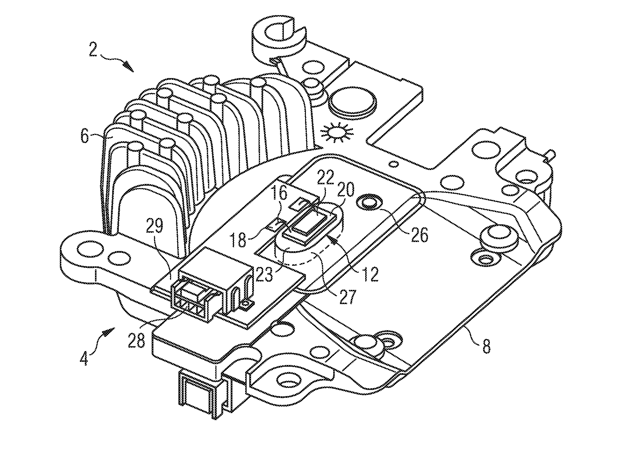
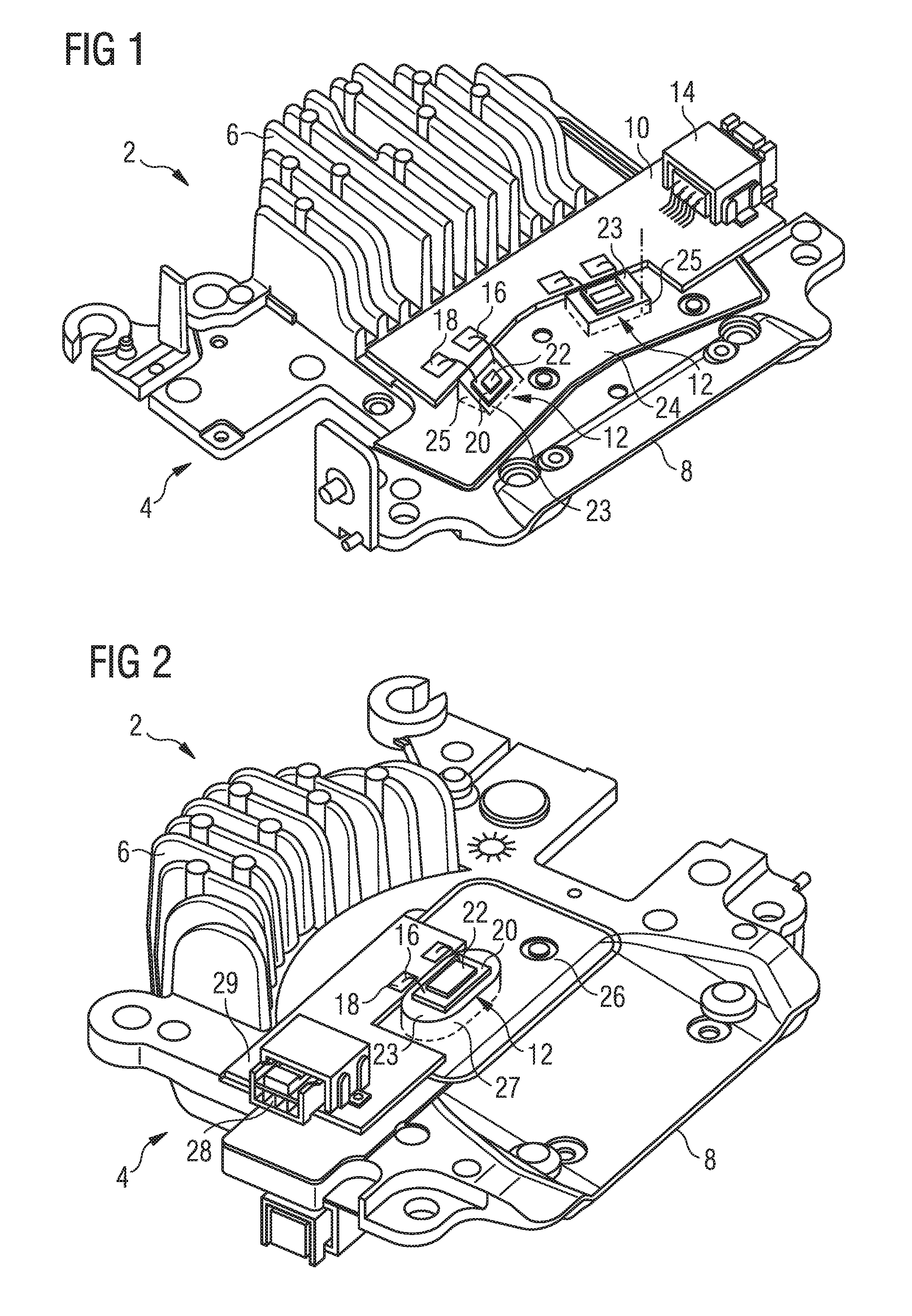
[0071]FIGS. 1 and 2 illustrate the invention. FIG. 1 is a perspective view of the top face of a support 2 for light sources of the light-emitting diode type 12. The support 2 comprises, essentially, a substrate 4 supporting the light-emitting diodes 12. More specifically, the substrate 4 of thermally conductive material, such as, for example, aluminum, comprises a base element or first portion 8 that is generally thin and flat and a second portion 6 forming cooling fins. The first and second portions 6, 8 are preferentially unitary, more preferentially integral with one another. The cooling fins 6 can extend in a direction that is generally transverse, preferentially at right angles, to the mean plane of the base element or first portion 8.

[0072]The top face 24 of the base element or first portion 8 comprises one or more structures 25 protruding relative to the generally planar base. Each structure 25 defines a reception or support plane, each of which supports the light-emitting di...

second embodiment

[0082]This second embodiment makes it possible to reduce the necessary number of power supply plates, more particularly to require only a single plate for two faces of a substrate, which is particularly advantageous.

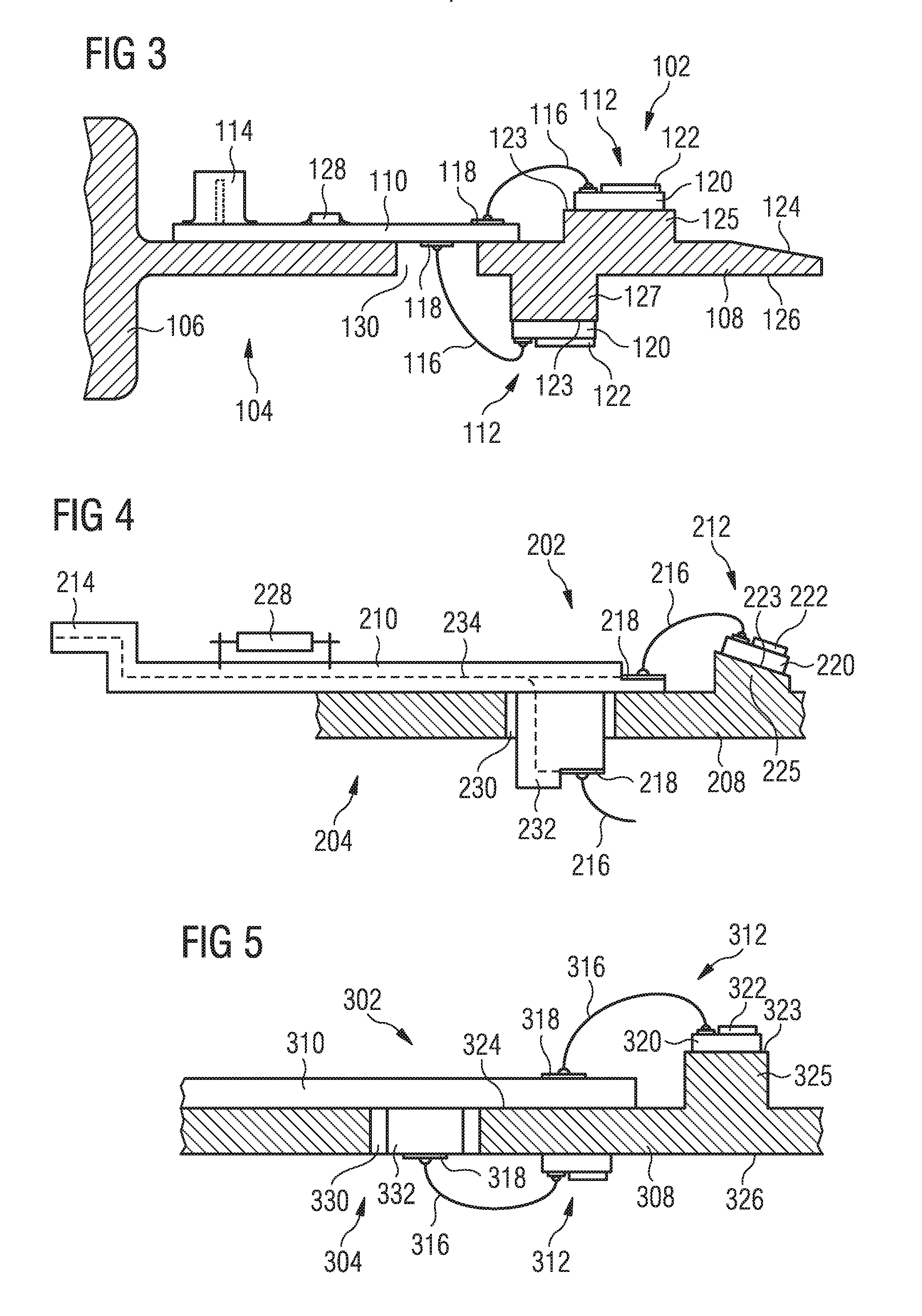
[0083]FIG. 4 illustrates a third embodiment of the invention. It is a view in longitudinal cross section of a diode support 202, like FIG. 3 of the second embodiment. The cross-sectional view is however partial, the rest of the support 202 not represented being similar to that of FIG. 3. The reference numbers of the second embodiment are used in the third embodiment for elements that are identical or similar, these numbers being uprated by 100 in order to clearly distinguish the two embodiments. Reference is moreover made for these elements to the corresponding description of the first embodiment. Specific numbers between 200 and 300 have been used for the specific elements.

[0084]The plate 210, instead of being essentially planar as in the first two embodiments of the in...


PUM


Abstract

A support for light source(s) for a lighting and/or light signaling module for a motor vehicle, comprising a substrate of thermally conductive material, preferentially of metallic material, at least one light source of the light-emitting or laser diode type with a face for mounting on the substrate, in thermal contact therewith and an electrical power supply circuit for the light source or sources. The power supply circuit is linked electrically with the light source or sources by means of metal wires soldered on the surface by the technology commonly referred to by the expression “wire bonding”. The measures of the invention make it possible to define at least one reception plane for the light sources oriented in such a way as to avoid having components in the vicinity of the light sources casting shadows thereon.

Description

CROSS-REFERENCE TO RELATED APPLICATIONS[0001]This application claims priority to the French application 1552365 filed on Mar. 23, 2015, which application is incorporated herein by reference and made a part hereof.BACKGROUND OF THE INVENTION[0002]1. Field of the Invention[0003]The invention deals with the field of lighting and / or of light signaling, notably for a motor vehicle. More particularly, the invention deals with the field of the mounting and the electrical connection of light sources of the light-emitting diode, LED, type. The invention deals with a support for light source(s) and a module comprising such a support.[0004]2. Description of the Related Art[0005]The use of light sources of light-emitting diode type in lighting and / or light signaling systems is increasingly widespread. In the field of motor vehicle lighting and light signaling, so-called power diodes are used. The latter are often generally planar and of the surface mount type. Surface-mounting of components con...

Claims


Application Information

Patent Timeline
Patent Type & Authority Applications(United States)
IPC IPC(8): F21S8/10F21W107/00
CPCF21S48/1104F21S48/115F21S48/215F21S48/321F21S48/212F21S48/328F21S43/50F21S41/50F21V19/001F21V23/06H01L33/62F21W2107/10H05K2201/10106H05K1/117H05K2203/049H01L2224/48091F21S41/19F21S41/192F21S41/147F21S43/195F21S43/14F21S45/47F21S41/148H01L2924/00014
Inventor ZOJCESKI, ZDRAVKODUARTE, MARCLAUVERNIER, DENIS
Owner VALEO VISION SA
Why Eureka
Try Eureka