Multitone Radar with Range Determination and Method of Use

a multi-tone radar and range determination technology, applied in the field of multi-tone radar with range determination and method of use, can solve the problems of high power-on-target required to generate a comparable signal-to-noise ratio (snr), warfighters encounter threats containing rf electronics, and it is difficult to distinguish background clutter using traditional linear radar, so as to achieve the effect of large system bandwidth

Active Publication Date: 2016-09-29
UNITED STATES OF AMERICA THE AS REPRESENTED BY THE SEC OF THE ARMY
View PDF3 Cites 47 Cited by
  • Summary
  • Abstract
  • Description
  • Claims
  • Application Information

AI Technical Summary

Benefits of technology

[0012]The present invention is directed to, inter alia, a method for exploiting both the magnitude and phase information available in the inter-modulation (intermod) products to create an “instantaneous” stepped frequency, non-linear target response. The new approach enables the operator to both maintain the unambiguous range dictated by the fundamental, multi-tone separation and obtain the entire target signature from a single transmitted waveform.
[0013]The present invention utilizes phase information from harmonics and intermod products, making it possible to measure the range to the target. In particular, the present invention records phase information for intermod products from many regularly spaced fr

Problems solved by technology

Its disadvantage, compared with traditional linear radar, is that the power-on-target required to generate a comparable signal-to-noise ratio (SNR) is much higher.
In the theater-of-operations, warfighters encounter threats that contain RF electronics.
Similarly, in the civilian world, there are instances when cellphones, smartphones, tablets and other “

Method used


Image

  • Multitone Radar with Range Determination and Method of Use
  • Multitone Radar with Range Determination and Method of Use
  • Multitone Radar with Range Determination and Method of Use

Examples


Embodiment Construction

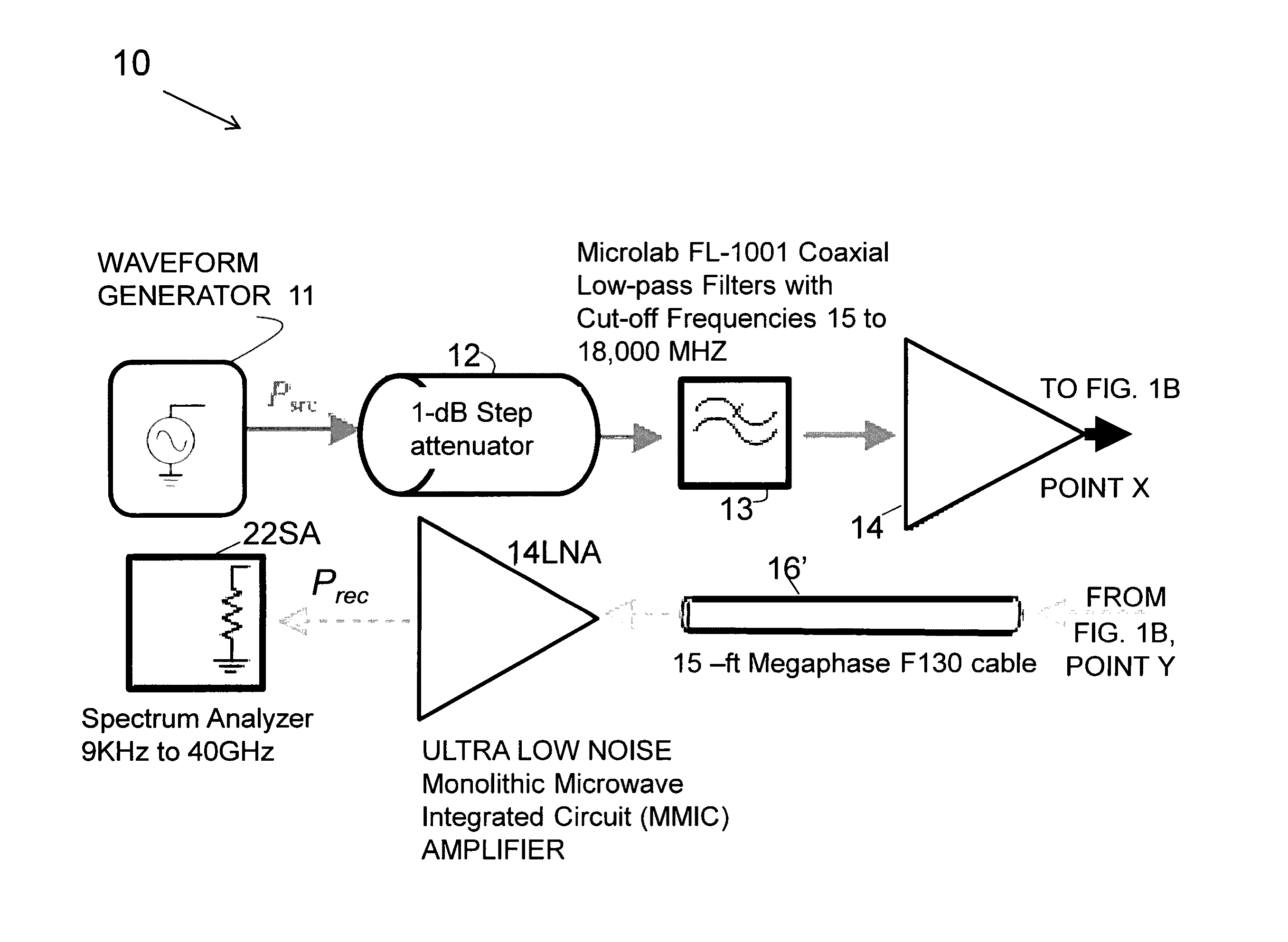
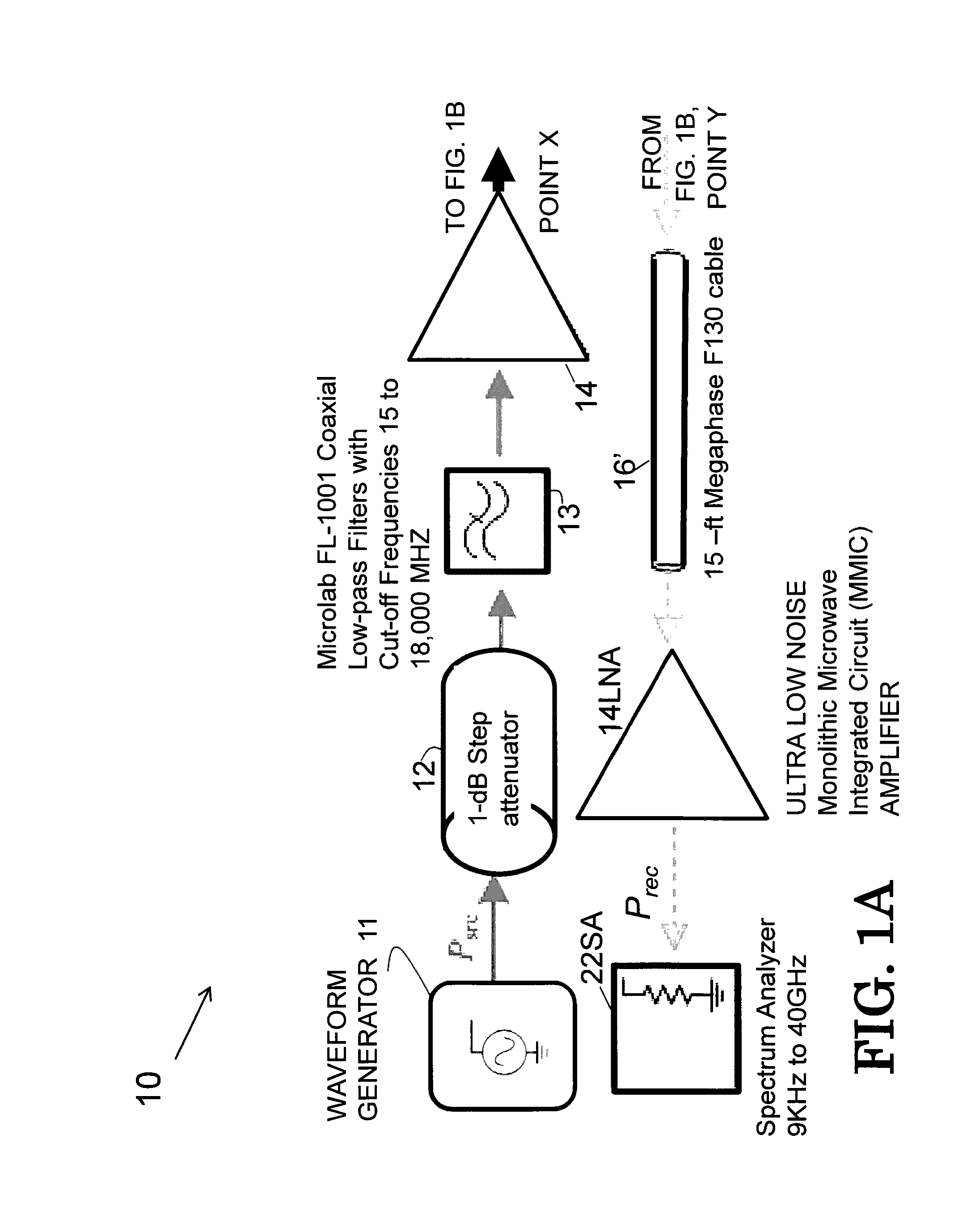
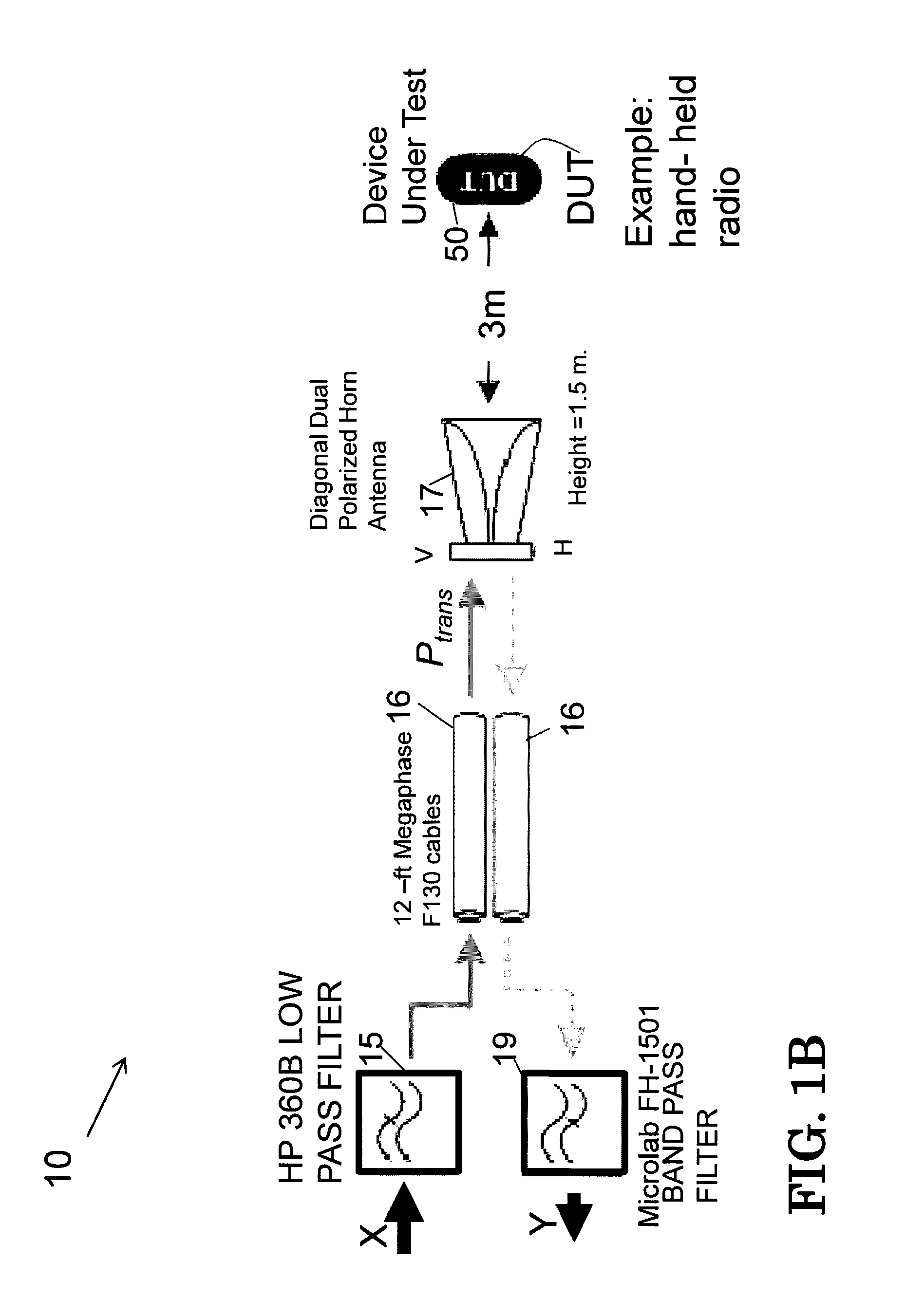
[0107]The embodiments of the invention and the various features and advantageous details thereof are explained more fully with reference to the non-limiting embodiments that are illustrated in the accompanying drawings and detailed in the following description. It should be noted that the features illustrated in the drawings are not necessarily drawn to scale. Descriptions of well-known components and processing techniques are omitted so as to not unnecessarily obscure the embodiments of the invention. The examples used herein are intended merely to facilitate an understanding of ways in which the embodiments of the invention may be practiced and to further enable those of skill in the art to practice the embodiments of the invention. Accordingly, the examples should not be construed as limiting the scope of the embodiments of the invention. Rather, these embodiments are provided so that this disclosure will be thorough and complete, and will fully convey the scope of the invention ...


PUM


Abstract

Method for determining distance to target using a multitone nonlinear radar system comprising providing a transmitter that transmits a signal comprising at least two predetermined frequency components; receiving transmitted signal upon reflection from target; determining the phase relationships of the frequency components when signal strikes target; determining distance the signal has travelled to target based upon the phase relationship of the frequency signal components at the time of reflection from target; computing the distance to target. A system comprising a transmitter subsystem that transmits radar signal comprising at least two frequency components; a receiver subsystem configured to receive a return signal comprising intermodulation and harmonic products; at least one processor configured to extract frequency samples from the return signal within a frequency range, apply a window function to the extracted frequency samples and perform an inverse fast Fourier transform on the resulting function to create a range profile.

Description

CROSS REFERENCE TO RELATED APPLICATION[0001]This application is a continuation-in-part application of and claims priority to U.S. patent application Ser. No. 13 / 870,519, entitled “Multitone Harmonic Radar and Method of Use,” by Dr. Gregory J. Mazzaro, et al., filed Apr. 25, 2013, and U.S. patent application Ser. No. 14 / 032,387 entitled “Combined Radar Assembly With Linear and Nonlinear Radar,” by Dr. Gregory J. Mazzaro, et al., filed Sep. 20, 2013, and published as US Patent Publication 2015 / 0084811 on Mar. 26, 2015, both of which are herein incorporated by reference in their entirety.STATEMENT OF GOVERNMENT INTEREST[0002]The invention described herein may be manufactured, used, and licensed by or for the United States Government without the payment of royalties.REFERENCE TO COMPUTER PROGRAM LISTING APPENDIX[0003]A computer program listing appendix, originally filed with U.S. patent application Ser. No. 14 / 032,387, has been submitted via EFS-Web labeled as “codeappendix” containing ...

Claims


Application Information

Patent Timeline
IPC IPC(8): G01S13/10G01S7/28
CPCG01S13/106G01S7/2813G01S13/103G01S7/292G01S7/414G01S13/887
Inventor MAZZARO, GREGORY J.RANNEY, KENNETH I.GALLAGHER, KYLE A.MARTONE, ANTHONY F.
Owner UNITED STATES OF AMERICA THE AS REPRESENTED BY THE SEC OF THE ARMY
Why Eureka
Try Eureka