
Charged particle - patient motion control system apparatus and method of use thereof

Active Publication Date: 2016-10-06
PROTOM INT HLDG CORP
View PDF10 Cites 13 Cited by
  • Summary
  • Abstract
  • Description
  • Claims
  • Application Information

AI Technical Summary

Benefits of technology

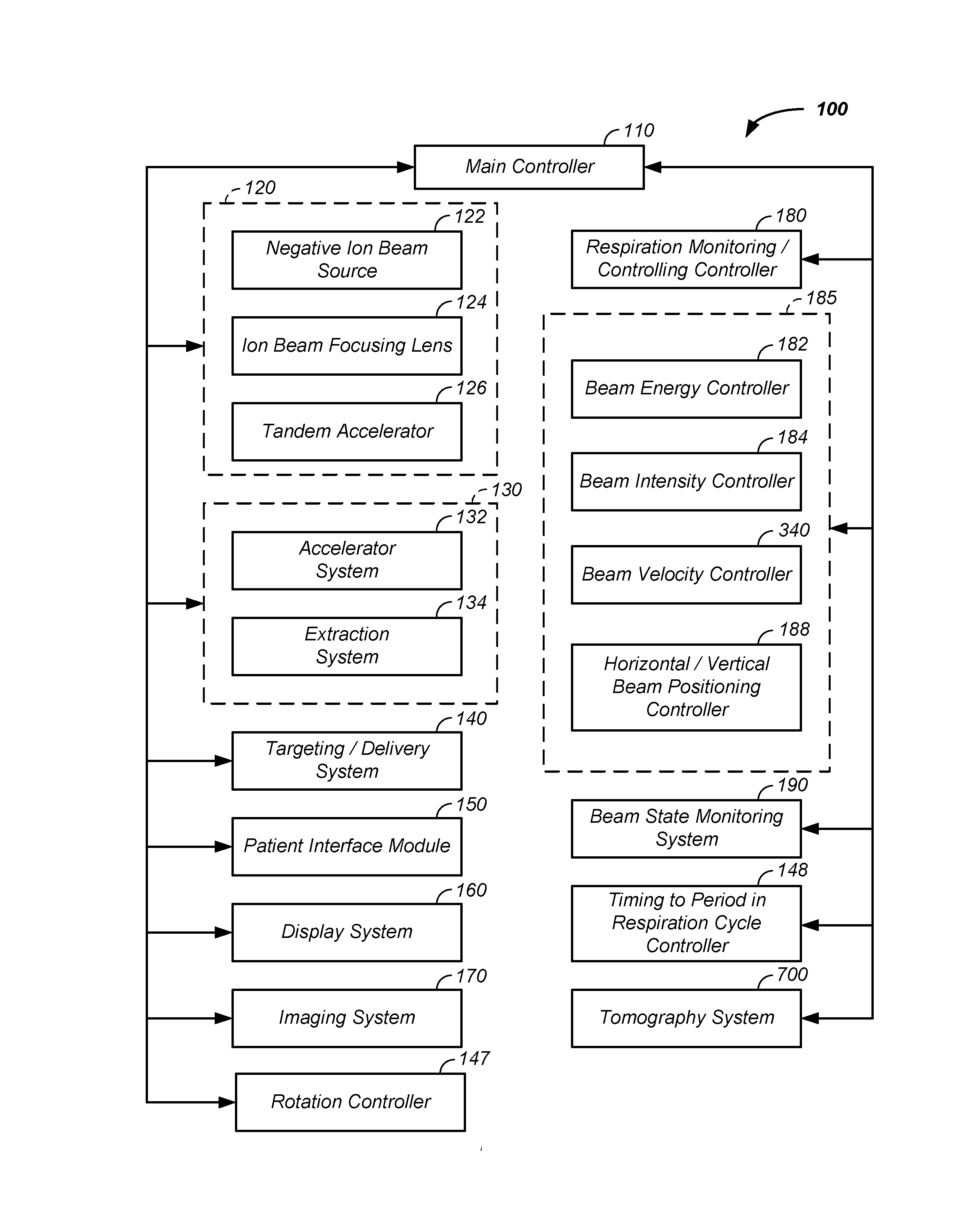
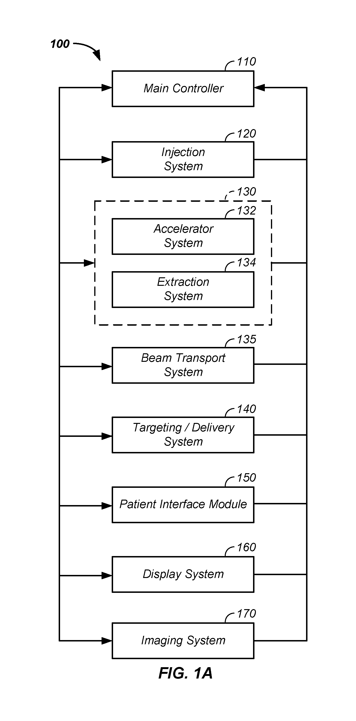
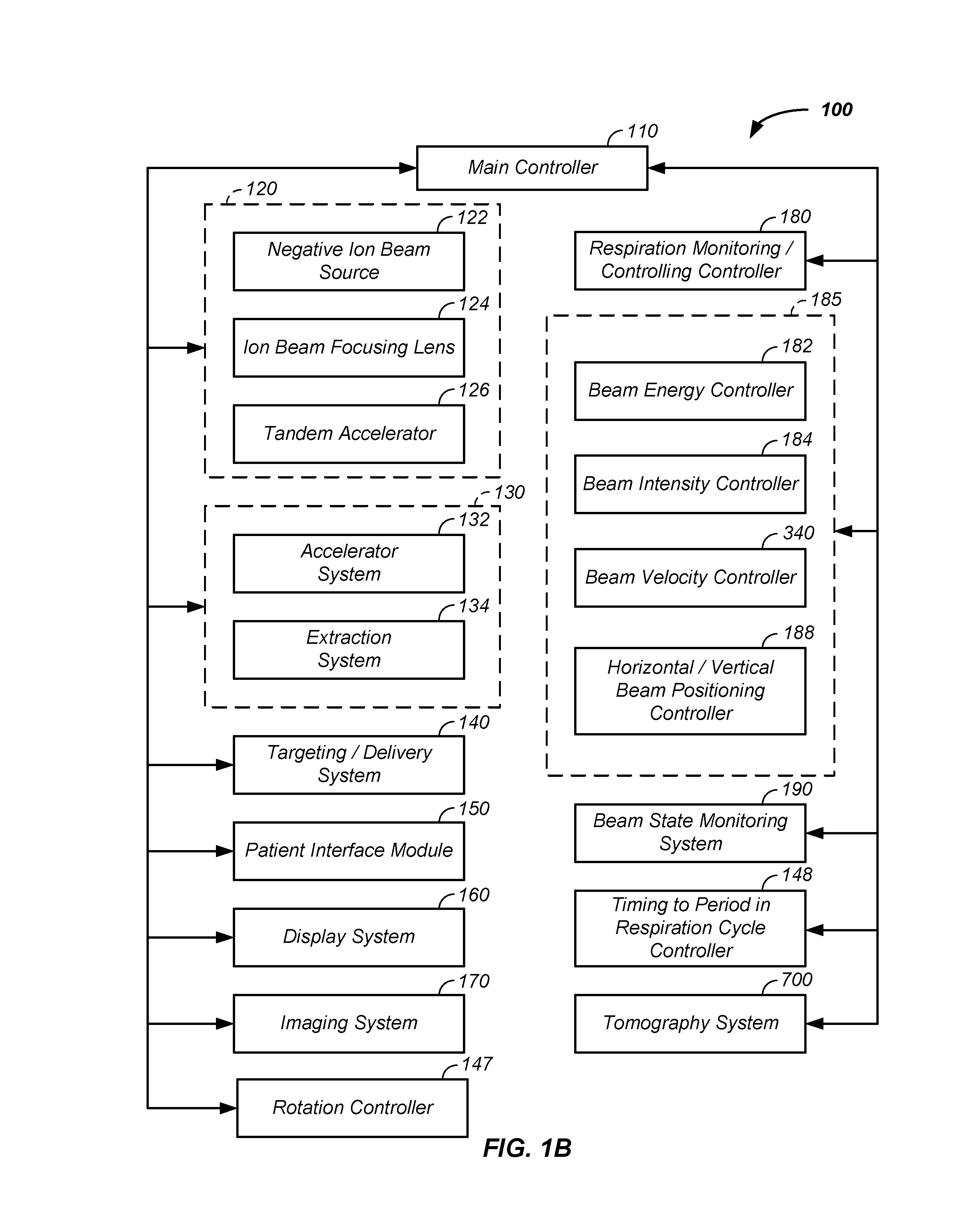
The invention is a system that controls the shape and direction of a charged particle beam relative to a patient or imaging system. This helps to improve the accuracy and precision of the treatment or imaging process.

Problems solved by technology

These particles damage the DNA of cells, ultimately causing their death.
Cancerous cells, because of their high rate of division and their reduced ability to repair damaged DNA, are particularly vulnerable to attack on their DNA.

Method used


Image

  • Charged particle - patient motion control system apparatus and method of use thereof
  • Charged particle - patient motion control system apparatus and method of use thereof
  • Charged particle - patient motion control system apparatus and method of use thereof

Examples


example iv

[0150]In a fourth example, the gantry comprises at least two imaging devices, where each imaging device moves with rotation of the gantry and where the two imaging devices view the patient 730 along two axes forming an angle of ninety degrees, in the range of eighty-five to ninety-five degrees, and / or in the range of seventy-five to one hundred five degrees.

Pendant

[0151]Referring still to FIG. 12A and referring now to FIG. 12B, a pendant system 1250, such as a system using the external pendant 1216 and / or internal pendent 1218 is described. In a first case, the external pendant 1216 and internal pendant 1218 have identical controls. In a second case, controls and / or functions of the external pendant 1216 intersect with controls and / or function of the internal pendant 1218. Particular processes and functions of the internal pendant 1218 are provided below, without loss of generality, to facilitate description of the external and internal pendants 1216, 1218. The internal pendant 1218...

example i

[0152]Referring now to FIG. 12B, a first example of the internal pendant 1218 is provided. In this example, in place of and / or in conjunction with a particular button, such as a first button 1270 and / or a second button 1280, moving or selecting a particular element, processes are optionally described, displayed, and / or selected within a flow process control unit 1260 of the internal pendant 1218. For example, one or more display screens and / or printed elements describe a set of processes, such as a first process 1261, a second process 1263, a third process 1265, and a fourth process 1267 and are selected through a touch screen selection process or via a selection button, such as a corresponding first selector 1262, second selector 1264, third selector 1266, and fourth selector 1268.

example ii

[0153]Referring still to FIG. 12B, a second example of the internal pendant 1218 is provided. In this example, one or more buttons or the like, such as the first button 1270, and / or one or more of the processes, such as the first process 1261, are customizable, such as to an often repeated set of steps and / or to steps particular to treatment of a given patient 730. The customizable element, such as the first button 1270, is optionally further setup, programmed, controlled, and / or limited via information received from the patient treatment module 1290. In this example, a button, or the like, operates as an emergency all stop button, which at the minimum shuts down the accelerator, redirects the charged particle beam to a beam stop separate from a path through the patient, or stops moving the patient 730.


PUM


Abstract

The invention comprises a system for controlling a charged particle beam shape and direction relative to a controlled and dynamically positioned patient and / or an imaging surface, such as a scintillation plate of a tomography system and / or a first two-dimensional imaging system coupled to a second two-dimensional imaging system. Multiple interlinked beam / patient / imaging control stations allow safe zone operation and clear interaction with the charged particle beam system and the patient. Both treatment and imaging are facilitated using automated sequences controlled with a work-flow control system.

Description

CROSS-REFERENCES TO RELATED APPLICATIONS[0001]This application is a continuation-in-part of U.S. patent application Ser. No. 15 / 167,617 filed May 27, 2016, which is:[0002]a continuation-in-part of U.S. patent application Ser. No. 15 / 152,479 filed May 11, 2016, which:[0003]is a continuation-in-part of U.S. patent application Ser. No. 14 / 216,788 filed Mar. 17, 2014,[0004]which is a continuation-in-part of U.S. patent application Ser. No. 13 / 087,096 filed Apr. 14, 2011, which claims benefit of U.S. provisional patent application No. 61 / 324,776 filed Apr. 16, 2010; and[0005]is a continuation-in-part of U.S. patent application Ser. No. 13 / 788,890 filed Mar. 7, 2013;[0006]is a continuation-in-part of U.S. patent application Ser. No. 14 / 952,817 filed Nov. 25, 2015, which is a continuation-in-part of U.S. patent application Ser. No. 14 / 293,861 filed Jun. 2, 2014, which is a continuation-in-part of U.S. patent application Ser. No. 12 / 985,039 filed Jan. 5, 2011, which claims the benefit of U....

Claims


Application Information

Patent Timeline
IPC IPC(8): A61N5/10
CPCA61N5/1081A61N5/107A61N5/1049A61N2005/1095A61N2005/1054A61N2005/1087A61N2005/1074A61N5/1082A61N5/1067G21K5/04A61N2005/105A61N2005/1097A61B6/032A61B6/4258A61B6/5205G21K1/08A61N5/1044
Inventor MICHAUD, SUSAN L.SPOTTS, STEPHEN L.BENNETT, JAMES P.LEE, W. DAVIS
Owner PROTOM INT HLDG CORP
Learn More