Coupling of photodetector array to optical demultiplexer outputs with index matched material

a photodetector array and optical demultiplexer technology, applied in the field of optical transceivers, can solve the problems of increasing the complexity of deployment and managing many fibers, increasing the complexity of alignment procedures, and increasing the cost of operation

Inactive Publication Date: 2016-10-06
APPLIED OPTOELECTRONICS
View PDF8 Cites 4 Cited by
  • Summary
  • Abstract
  • Description
  • Claims
  • Application Information

AI Technical Summary

Problems solved by technology

As the number of subscribers connected to the network increases and the fiber count increases rapidly, deploying and managing many fibers becomes complex and expensive.
One challenge in developing such a PON is utilizing the capacity in the trunk fiber efficiently in order to transmit the maximum possible amount of information on the trunk f

Method used


Image

  • Coupling of photodetector array to optical demultiplexer outputs with index matched material
  • Coupling of photodetector array to optical demultiplexer outputs with index matched material
  • Coupling of photodetector array to optical demultiplexer outputs with index matched material

Examples


Embodiment Construction

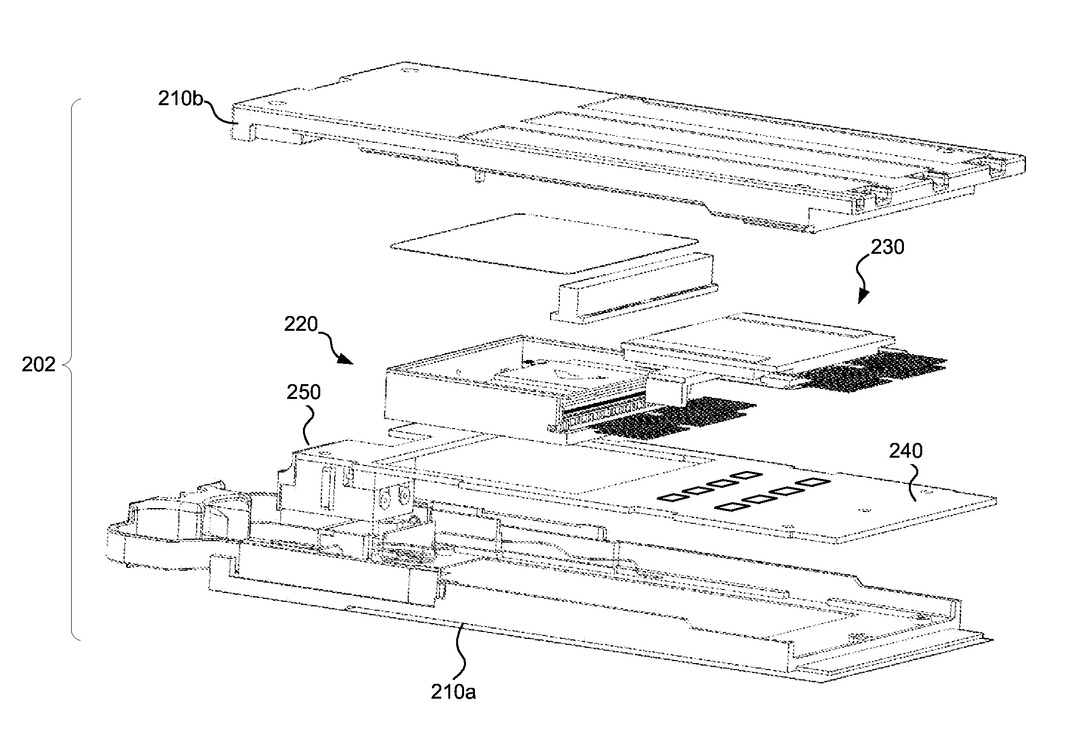
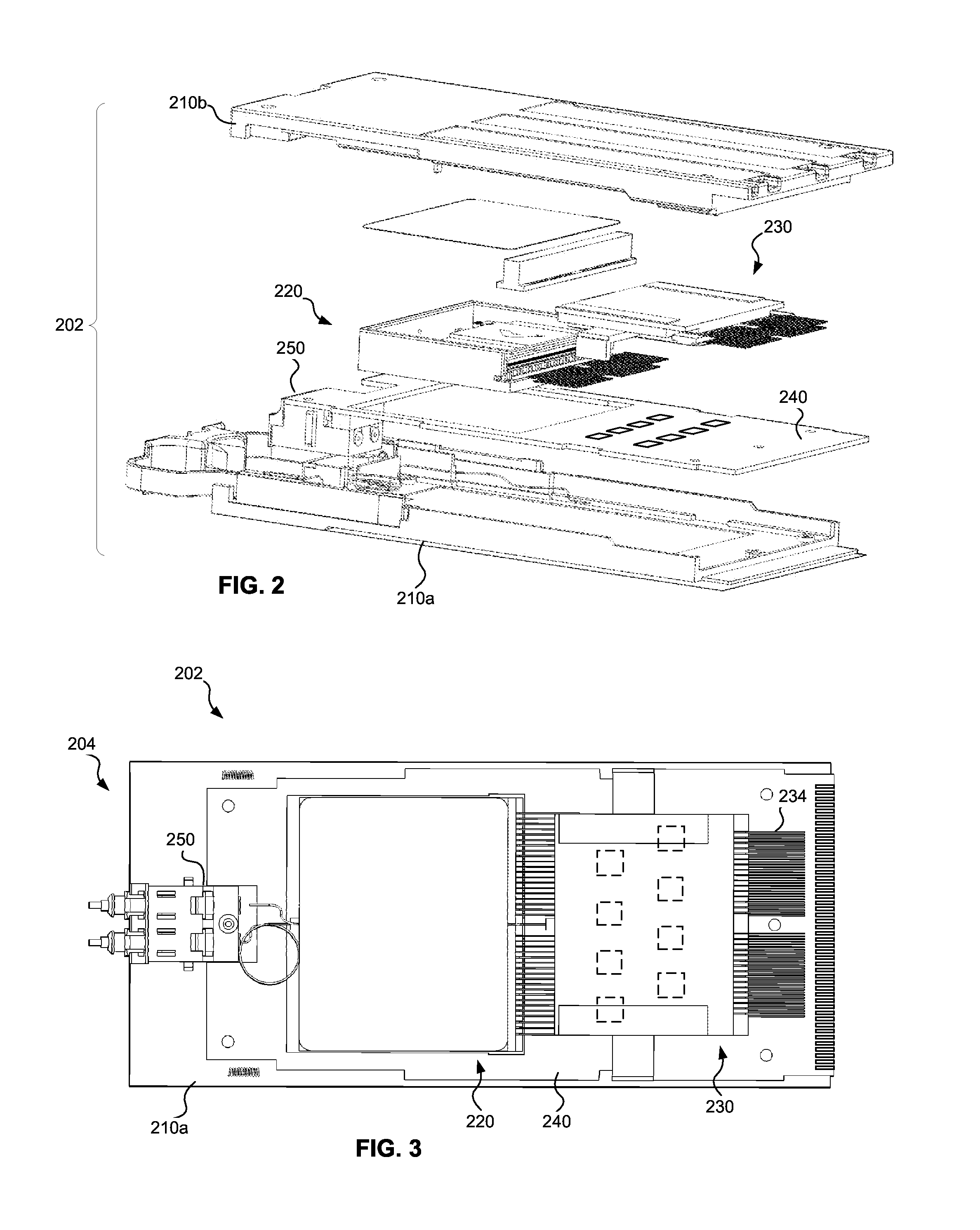
[0016]A multi-channel receiver optical subassembly (ROSA), consistent with embodiments described herein, includes an optical demultiplexer, such as an arrayed waveguide grating (AWG), with outputs optically coupled to respective photodetectors such as photodiodes. In one embodiment, the system may include an optical demultiplexer including multiple optical outputs corresponding to multiple signal channels and a photodetector array including a plurality of photodiodes aligned with the multiple optical outputs. The system may also include an epoxy, or other suitable material, to serve as a coupling medium, disposed within a gap between each of the photodiodes and each of the corresponding optical outputs of the optical demultiplexer. The epoxy may be configured to provide an index of refraction that is matched to the optical demultiplexer to improve optical coupling to the photodiodes.

[0017]A compact multi-channel optical transceiver may include the multi-channel ROSA, and the optical...


PUM


Abstract

A system is provided for improved coupling of photodetectors to optical demultiplexer outputs, for example an arrayed waveguide grating (AWG), using a refractive index matched material. In one embodiment, the system may include an optical demultiplexer including multiple optical outputs corresponding to multiple signal channels and a photodetector array including a plurality of photodiodes aligned with the multiple optical outputs. The system may also include an epoxy disposed within a gap between each of the photodiodes and each of the corresponding optical outputs of the optical demultiplexer. The epoxy may be configured to provide an index of refraction that is matched to the optical demultiplexer.

Description

TECHNICAL FIELD[0001]The present disclosure relates to optical transceivers and more particularly, to improved coupling of photodetectors to optical demultiplexer outputs with a refractive index matched material.BACKGROUND INFORMATION[0002]Optical communications networks, at one time, were generally “point to point” type networks including a transmitter and a receiver connected by an optical fiber. Such networks are relatively easy to construct but deploy many fibers to connect multiple users. As the number of subscribers connected to the network increases and the fiber count increases rapidly, deploying and managing many fibers becomes complex and expensive.[0003]A passive optical network (PON) addresses this problem by using a single “trunk” fiber from a transmitting end of the network, such as an optical line terminal (OLT), to a remote branching point, which may be up to 20 km or more. One challenge in developing such a PON is utilizing the capacity in the trunk fiber efficientl...

Claims


Application Information

Patent Timeline
IPC IPC(8): G02B6/42G02B6/293
CPCG02B6/4212G02B6/2938G02B6/29304G02B6/4274G02B6/425G02B6/12019
Inventor ZHENG, JUNHO, I-LUNGWANG, YI
Owner APPLIED OPTOELECTRONICS
Why Eureka
Try Eureka