Miniature stabilized unmanned aerial vehicle gimbal

a technology of unmanned aerial vehicles and gimbals, which is applied in the direction of toy aircrafts, process and machine control, instruments, etc., can solve the problems of poor performance of servo driven gimbals, affecting the operation of the system, etc., and achieves the effect of high bandwidth

Active Publication Date: 2016-10-06
VANTAGE ROBOTICS LLC
View PDF2 Cites 68 Cited by
  • Summary
  • Abstract
  • Description
  • Claims
  • Application Information

AI Technical Summary

Problems solved by technology

Any rotation of the image sensor creates large changes in what is captured within the field of view of the image sensor, resulting in distorted, shaky and blurred images.
The servo driven gimbals are generally very slow and inferior in performance to brushless motor gimbals.
In general a brushless motor gimbal does not have sufficient power to drive the system at high frequencies.
It is also challenging to sense small amplitude and high frequency movements because of noise in the sensor.
Adding mass to the stabilized platform also lowers the natural frequency but is undesirable especially for a UAV where minimizing weight and size is important to safety, flight endurance, and flight performance.

Method used


Image

  • Miniature stabilized unmanned aerial vehicle gimbal
  • Miniature stabilized unmanned aerial vehicle gimbal
  • Miniature stabilized unmanned aerial vehicle gimbal

Examples


Embodiment Construction

Hardware

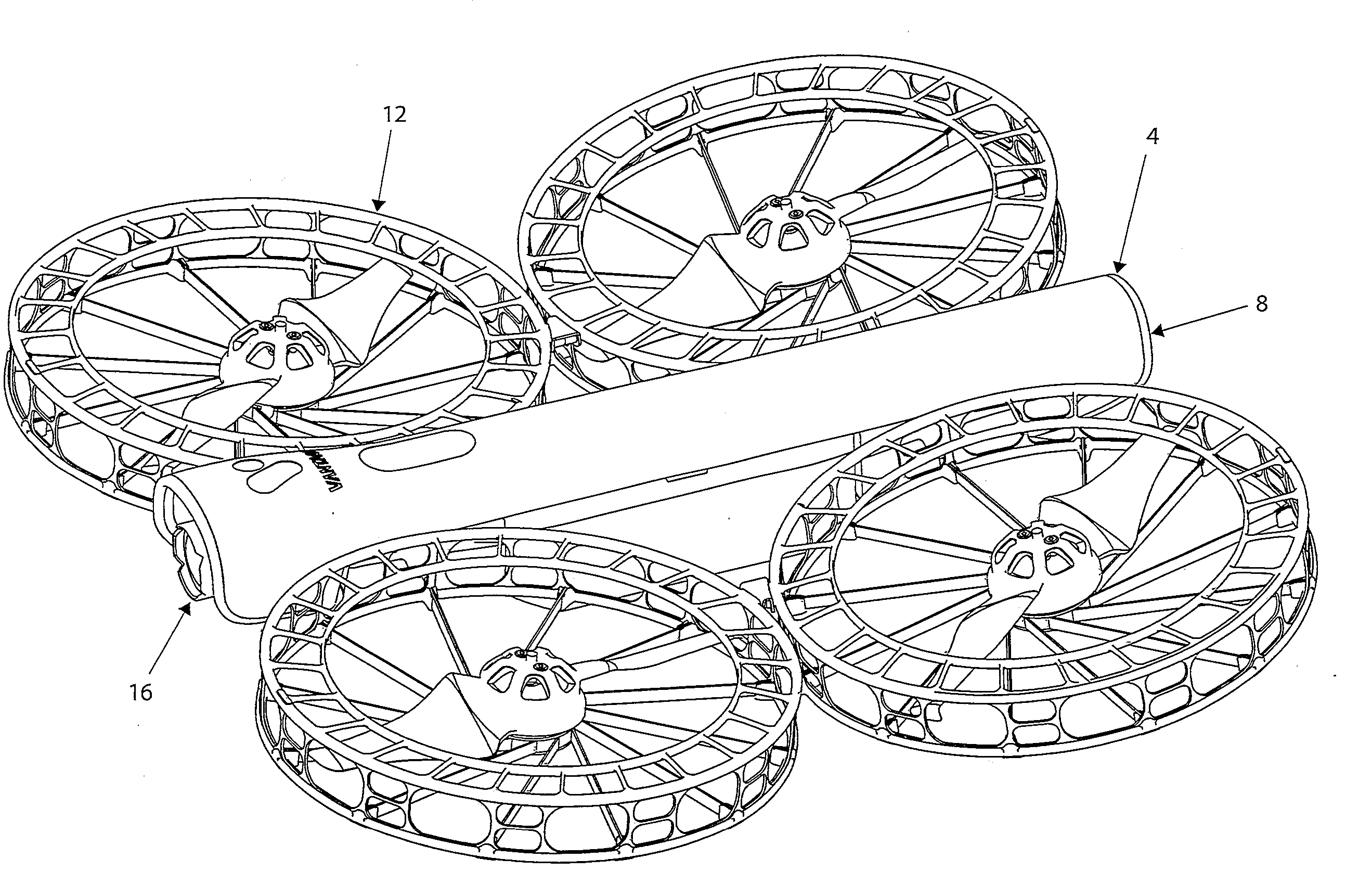
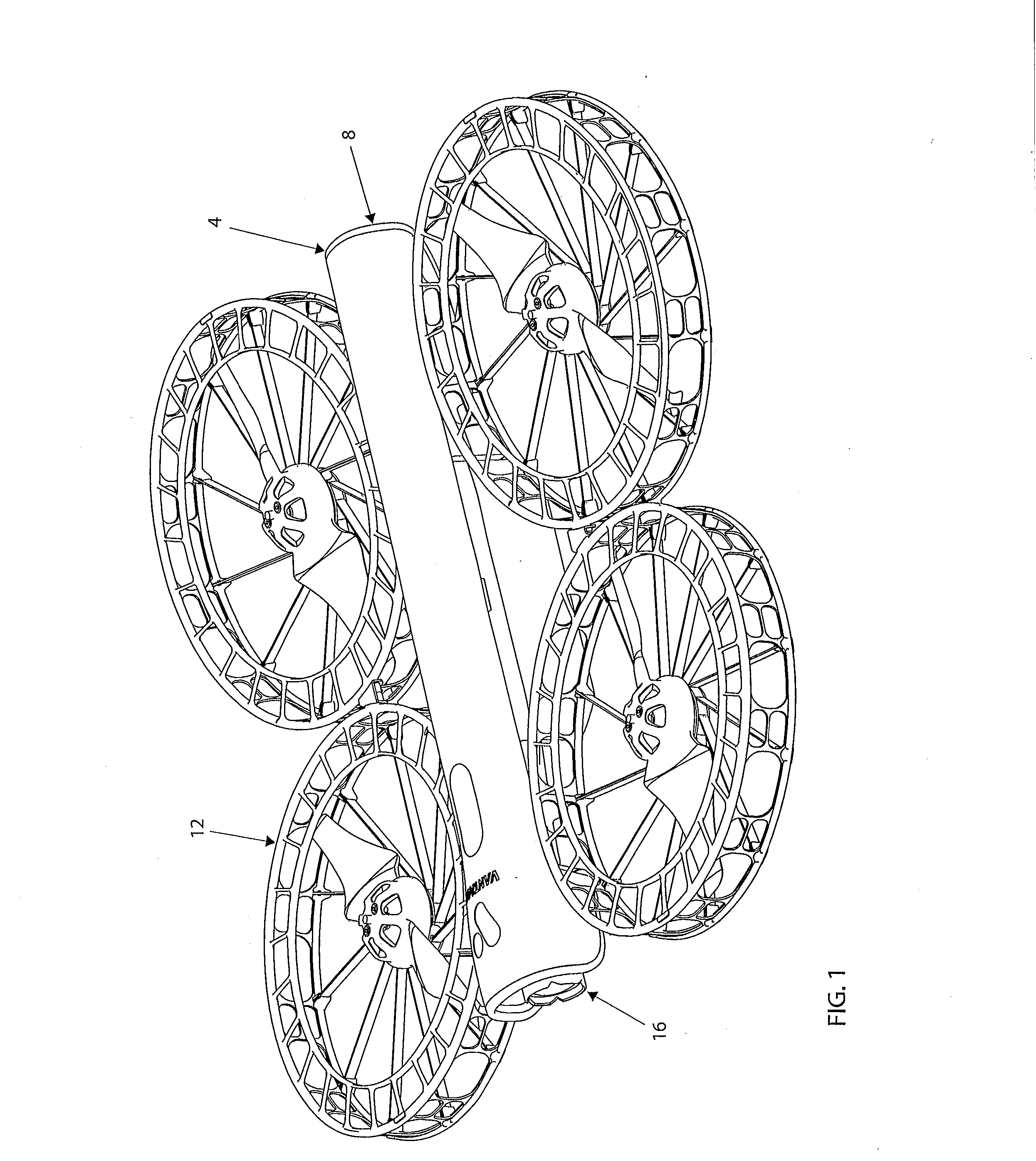
[0023]Referring now to FIG. 1 a UAV 4 is comprised of a fuselage 8, a thrust pod assembly 12, a battery 18, and a gimbal 16. Fuselage 8 and battery 18 each include electronic processing and flight control sub-systems that would be familiar to one skilled in the art of UAV design and will not be described in detail. Likewise the basic composition, components, and function of the thrust pods 12 will not be described in detail.

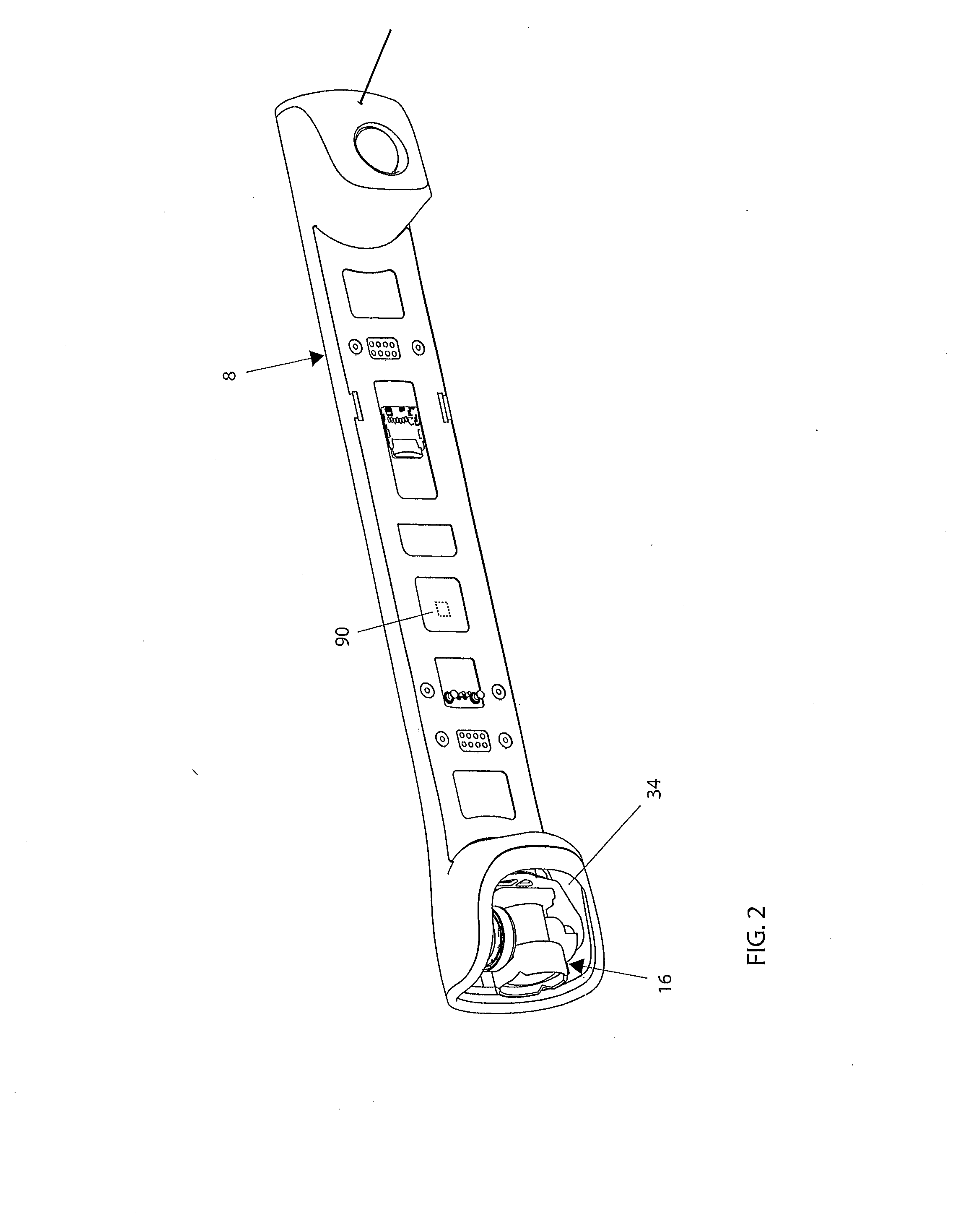
[0024]Referring now to FIG. 2, the location and orientation of gimbal 16 in relation to fuselage 8 is shown. A gimbal cavity 34 is a molded concave form integral to fuselage 8 that substantially shields gimbal 16 from impacts with objects or the ground. In another embodiment, an optically clear dome-shaped shield is fastened to the front of fuselage to further protect gimbal 16.

[0025]FIG. 3 shows 2-axis gimbal 16. FIG. 4 shows an exploded assembly view of gimbal 16. A pitch stage sub-assembly 24 is rotationally attached to a roll stage 20 sub-assembly, wh...


PUM


Abstract

Embodiments discussed herein provide improved control of an unmanned aerial vehicle camera gimbal. In some embodiments, a linear control circuit is described that uses an operational amplifier that allows the system to retain its passive isolation of high frequency disturbances.

Description

CROSS-REFERENCE TO RELATED APPLICATIONS[0001]This application claims priority to U.S. Provisional Application No. 62 / 141,141, filed Mar. 31, 2015 and entitled “MECHANICAL ROTARY STABILIZATION OF IMAGE SENSORS,” which is hereby incorporated by reference in its entirety.BACKGROUND[0002]1. Technical Field[0003]Embodiments disclosed herein relate generally to the mechanical rotary stabilization of image sensors used for taking photographs or video from an aerial vehicle. While the embodiments disclosed herein may be applicable to a wide range of aircraft, certain embodiments may be particularly applicable to multi-rotor unmanned aerial vehicles (UAVs). Certain embodiments are applicable to a wide range of multi-rotor UAVs, but especially designed for quadrotor UAVs.[0004]2. Description of the Related Art[0005]UAVs are increasingly being used to capture videos and photographs during flight. When capturing videos or photographs (images) it is desirable that the images are free of any unde...

Claims


Application Information

Patent Timeline
Patent Type & Authority Applications(United States)
IPC IPC(8): G03B15/00F16M11/12G05D3/14B64C39/02H02P7/288G03B17/56F16M13/02F16M11/18
CPCG03B15/006F16M13/022F16M11/125F16M11/18B64C2201/127H02P7/288G03B17/561G05D3/1409B64C39/024B64D47/08A63H27/12G03B2217/005F16M11/10F16M11/2028H02P6/08G03B17/56B64U2101/30
Inventor FISHER, SR., TOBINVAN NIEKERK, JOHANNES BECKERJANIK, CRAIG
Owner VANTAGE ROBOTICS LLC
Why Eureka
Try Eureka