Slider and Handling Tool for Slider

Active Publication Date: 2016-10-13
YKK CORP
View PDF3 Cites 2 Cited by
  • Summary
  • Abstract
  • Description
  • Claims
  • Application Information

AI Technical Summary

Benefits of technology

[0051]The slider of the present invention has a slider body made of synthetic resin in which a tab attaching part allowing a tab to be attached to is removed from an upper blade part and a lower blade part, and a slider handling tool which is independently formed from the slider body and holds a top and a bottom of the slider body in a height direction thereof.
[0052]Since the slider of the present invention has a slider body made of synthetic resin and without having a tab, the slider body itself can be lightweight. Further, when the slider is in mass production, there is no need to provide a tab attaching part such as a tab attaching post to each slider body as well as to produce a tab, which results in reduced production cost of the slider. In addition, the slider of the present invention does not make a contact noise between the slider body and the tab, as in the conventional type, and quietness of a slide fastener can be significantly improved.
[0053]The slider body of the present invention is made of synthetic resin, and when the slider body is attached to element rows of left and right fastener stringers to slide in a coupling direction of the element rows, the slider body can be slid while being held at a top and a bottom of the slider body with a slider handling tool.
[0054]With the above, sliding of the slider body can be

Problems solved by technology

However, the slider body 90 cannot b

Method used


Image

  • Slider and Handling Tool for Slider
  • Slider and Handling Tool for Slider
  • Slider and Handling Tool for Slider

Examples


example 1

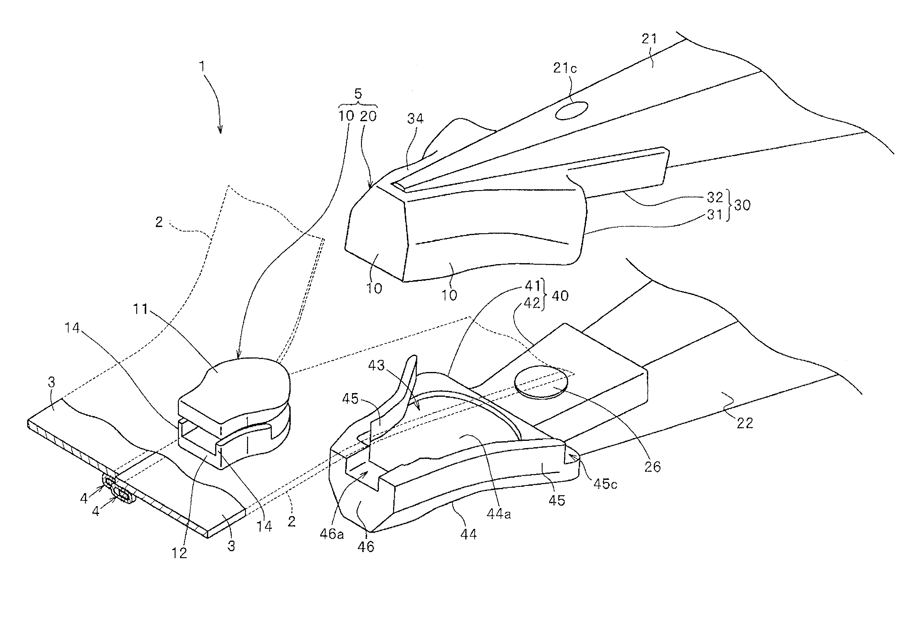
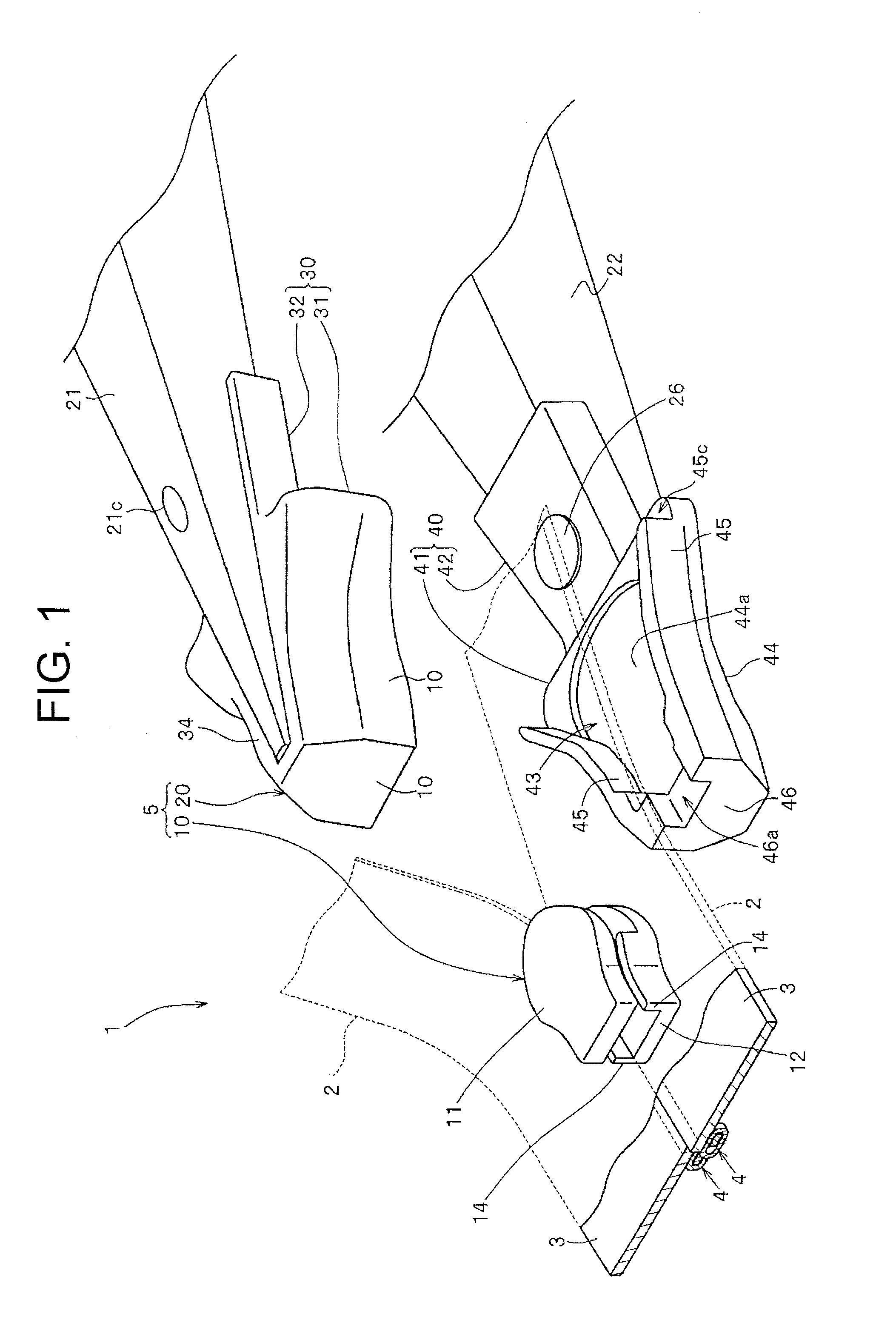
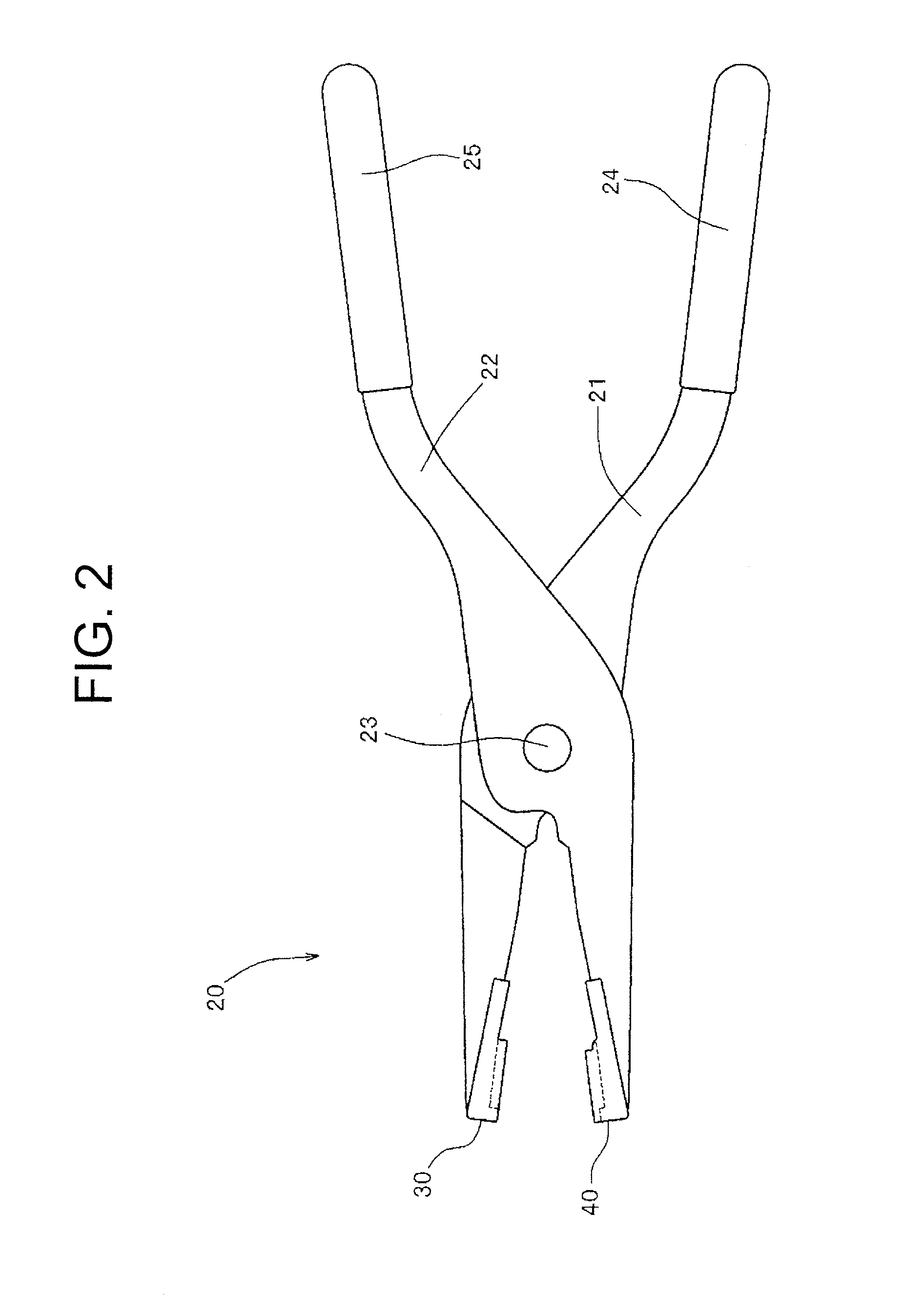
[0095]FIG. 1 shows a perspective view of a slide fastener according to Example 1 of the present invention. FIG. 2 is an overall view of a slider handling tool used for the slide fastener. FIGS. 3 to 5 show a first holding part of the slider handling tool. FIGS. 6 to 8 show a second holding part of the slider handling tool.

[0096]In below explanations, front and back direction means a tape length direction of a fastener tape. Particularly, a direction sliding a slider body when left and right element rows are coupled is called “frontward”, and a direction sliding the slider when the coupled elements are separated (opened) is called “backward”.

[0097]Also, left and right direction means a tape width direction of a fastener tape. Top and bottom direction means a tape top and bottom direction of a fastener tape. Specifically, when a slide fastener is attached to a fastener attached member (seat cover), a direction of an outer surface side (or top surface side) of the fastener attached mem...

example 2

[0187]FIG. 14 is a cross-sectional view of the slider body and the slider handling tool according to Example 2. FIG. 15 is an explanatory view explaining a state that the slider body is held with the slider handling tool.

[0188]Regarding a slider 6 of Example 2, an engaged concave part 15 is formed on an upper surface of the upper blade part 11b and a lower surface of the lower blade part 12b in the slider body 10b, a whole upper surface of the upper blade part 11b and a whole lower surface of the lower blade part 12b are not formed as a flat surface, and engaging convex parts 57 and 67 which are inserted into the engaged concave part 15 of the upper blade part 11b and the lower blade part 12b are respectively disposed on an upper supporting surface 54a of the first holding part 50 and a lower blade part supporting surface 64a of the second holding part 60, respectively.

[0189]It should be noted that the slider 6 of the Example 2 has a similar structure to the slider 5 of Example 1 as...

example 3

[0212]FIG. 16 is a cross-sectional view of a slider body and a slider handling tool regarding Example 3. FIG. 17 is an explanatory view explaining a state that the slider body is held with the slider handling tool.

[0213]The slide fastener of Example 3 includes a pair of left and right fastener stringers in which coil-like element rows are formed on a surface of a tape along facing tape side edge parts of left and right fastener tapes, first and second stopping elements disposed adjacent to the element rows at front and back end parts of each fastener stringer, and a slider body 10c disposed slidably along the element rows, which are not shown. Further, in the slide fastener of Example 3, a slider handling tool 20c for sliding operation of the slider body 10c as a slider 7 is independently prepared from the slider body 10c.

[0214]The left and right fastener stringers in Example 3 are formed as fastener stringers for a general type “top surface” slide fastener in which the element row...


PUM


Abstract

Provided is a slider which is lightweight, reduces production cost and is excellent in quietness, the slider having a slider body which is hardly deformed or broken. The slider includes a slider body made of synthetic resin and a slider handling tool which holds a top and bottom of the slider body and performs sliding operation. The slider handling tool has first and second arm parts connecting with a connecting axis part and first and second holding parts disposed at a tip end part of the first and second arm parts, respectively.

Description

CROSS-REFERENCE TO RELATED APPLICATION[0001]The present application claims priority of Japanese Patent Application No. 2015-080269, filed on Apr. 9, 2015 and entitled “Slider and Handling Tool for Slider”, the entire contents of which are hereby incorporated by reference.TECHNICAL FIELD[0002]The invention relates to a slider in which a slider body without having a tab is operated to slide with a handling tool formed independently from the slider body.BACKGROUND ART[0003]Generally, a slide fastener includes a pair of left and right fastener stringers in which element rows are formed on side edges facing each other of left and right fastener tapes along a length direction of the tape, and a slider attached to the element rows in a slidable manner. By sliding the slider along the element rows in a coupling direction or a separating direction of fastener elements, the slide fastener can be closed or opened.[0004]A slider generally includes a slider body and a tab rotatably attached to t...

Claims


Application Information

Patent Timeline
IPC IPC(8): A44B19/26B25B7/00A47G25/90
CPCA44B19/26B25B7/00A47G25/902A44B19/262A44B19/30B25B7/02A44B19/267A45C13/103A44D2200/10B60R21/207B60R2021/2076
Inventor YAMAZAKI, MAKOTOYAMASHITA, YUICHI
Owner YKK CORP
Why Eureka
Try Eureka